background image

You can drag or flick a Search badge to the right, off the display, to delete it. You can bring the badge back by swiping in from the right.

Signal clipping and badges

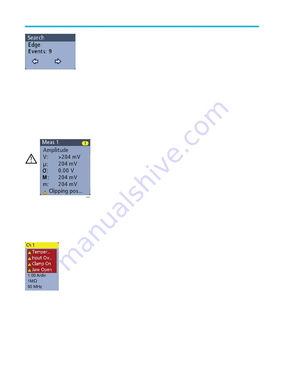
Clipping causes inaccurate amplitude-related measurement results. Clipping also causes inaccurate amplitude values in saved waveform
files. If a math waveform is clipped, it will not affect amplitude measurements on that math waveform.

Warning: Clipping is caused by excessive or dangerous voltages at the probe tip and/or a vertical scale setting that is not
adequate to display the entire vertical range of the waveform. Excessive voltage at the probe tip can injure the operator and cause
damage to the probe and/or instrument.

This instrument shows a warning triangle symbol and the word Clipping in a Channel badge when a vertical clipping condition
exists. Any measurement badges associated with that channel also indicate a clipping condition.

To close the clipping message, change the vertical scale to show the entire waveform, disconnect the probe tip from the excessive
voltage source, and check that you are probing the correct signal using the correct probe.

Error messages and badges

This instrument shows a warning triangle symbol and an error message abbreviation in a Channel badge when an error occurs.

To remove the message from the badge, clear the error.

System badges

System badges (in the Settings bar) display the main Horizontal, Trigger, and Acquisition settings. You cannot delete System badges.

Getting acquainted with your instrument

3 Series Mixed Domain Oscilloscope Printable Help

52

Summary of Contents for 3 Series

Page 1: ...ified personnel only To avoid personal injury do not perform any servicing unless you are qualified to do so Refer to all safety summaries prior to performing service Supports Product Firmware V1 10 0 and later Register now Click the following link to protect your product www tek com register P 077149702 077 1497 02 ...

Page 2: ...l Public License GPL or Lesser GNU General Public License LGPL the complete corresponding sources are available You can order a CD containing the sources from us for a period of three years after download of the software by sending a written request to Chief Intellectual Property Counsel Tektronix Inc MS 50 LAW 14150 SW Karl Braun Dr Beaverton OR 97077 This offer is valid to anyone in receipt of t...

Page 3: ...sis option 26 Application bundle 27 Power cord options 27 Service options 27 Option upgrades 29 Post purchase instrument options 29 Bandwidth upgrade options 29 How to install an option license 30 Install your instrument 32 Check shipped accessories 32 Safely rotate the handle 32 Operating requirements 33 Input signal requirements 33 Powering the oscilloscope 34 Check that the oscilloscope passes ...

Page 4: ...ntion guidelines 65 Analog channel operating basics 66 Acquiring a signal 66 Quickly display a waveform autoset 66 Set horizontal parameters 67 How to trigger on a signal 67 Set the acquisition mode 68 Start and stop an acquisition 69 Add a channel waveform to the display 69 Configure channel or waveform settings 70 Add a math reference or bus waveform 71 Add a measurement 72 Configure a measureme...

Page 5: ... Reference waveform 99 Recall a Setup file 99 Menus and dialog boxes 100 The Acquisition configuration menu 100 Add Measurements configuration menu overview 101 Amplitude Measurements panel 102 Time Measurements panel 104 Other Measurements panel 105 The Power Measurements panel optional 106 Measurement configuration menu 111 Measurement Name panel Measurement configuration menu 111 Global Measure...

Page 6: ...nu 155 Pulse Width Search configuration menu 155 Rise Fall Time Search configuration menu 156 Runt Search configuration menu 158 Setup and Hold Search configuration menu 159 Setup and Hold Search Define Inputs configuration menu 160 Timeout Search configuration menu 160 Analog Channel configuration menu 161 Probe Setup panel Channel configuration menu 163 Probe Compensation configuration menu anal...

Page 7: ...r configuration 199 ARINC429 serial bus trigger settings panel 200 Audio serial bus trigger settings panel 201 CAN serial bus trigger settings panel 202 FlexRay serial bus trigger settings panel 204 I2C serial bus trigger settings panel 206 LIN serial bus trigger settings panel 207 MIL STD 1553 serial bus trigger settings panel 209 Parallel serial bus trigger settings panel 211 RS 232 serial bus t...

Page 8: ...ncy Domain menu 239 RF waveform view and badges 239 Spectrum trace handle 240 Spectrum trace markers 241 The RF waveform view user interface 241 Using spectral analysis controls 242 Setting up the RF input 242 Resolution bandwidth 243 Spectrogram display 244 Automatic peak markers 245 Frequency domain cursors 245 Use the Arbitrary Function Generator 246 Triggering concepts 250 Trigger sources 250 ...

Page 9: ...59 Using cursor readouts 260 Using XY Cursors 260 Measurement variables 260 Missing or out of range samples 262 Math waveforms 262 Math waveform elements 262 Guidelines for working with math waveforms 263 Math waveform editor syntax 263 Math waveform differentiation 264 Math waveform offset position and scale 264 Waveform integration 264 Using math waveforms 265 Using advanced math 266 Using FFT 2...

Page 10: ...s 241 Figure 7 Lower narrower RBWs take longer to process but have finer frequency resolution and a lower noise floor 244 Figure 8 Higher wider RBWs take less time to process but have less frequency resolution and a higher noise floor 244 Figure 9 The channel 1 sine wave shows the output of the AFG The channel 2 square wave show the output of the AFG sync pulse It comes from the AUX OUT port 248 L...

Page 11: ...26 Table 7 3 Series power option 26 Table 8 3 Series bundle option 27 Table 9 Instrument upgrade options 29 Table 10 MDO32 bandwidth upgrades 30 Table 11 MDO34 bandwidth upgrades 30 Table 12 Maximum analog input 33 Table 13 Maximum input with a P6316 Digital Probe 34 Table 14 Common touchscreen UI tasks with mouse equivalents 55 Table 15 Security configuration menu fields and controls 189 List of ...

Page 12: ...LE THE UNUSED SOFTWARE AND ANY ACCOMPANYING DOCUMENTATION SHOULD BE RETURNED PROMPTLY TO TEKTRONIX WITHIN 30 DAYS OF PURCHASE FOR A FULL REFUND OF THE LICENSE FEE PAID FOR INFORMATION REGARDING THE RETURN OF SOFTWARE ENCODED OR INCORPORATED WITHIN EQUIPMENT CONTACT THE NEAREST TEKTRONIX SALES OFFICE DEFINITIONS Equipment means Tektronix equipment that the Software is encoded or incorporated within...

Page 13: ...ent including without limitation identifying potential errors and improvements any comments questions suggestions or the like Feedback Tektronix is free to use such Feedback without any attribution compensation or restriction in any manner to improve or enhance its products irrespective of any other obligation or limitation between the Parties governing such Feedback You hereby grant Tektronix an ...

Page 14: ... performs any remedial upgrade or other work on Your systems including any Equipment If applicable law prohibits exclusion of liability for lost data then Tektronix will only be liable for the cost of the typical effort to recover the lost data from Your last available back up SECURITY DISCLAIMER This Software and its associated Equipment are not designed or intended to be used with unsecure netwo...

Page 15: ...t shall not constitute or be deemed a subsequent waiver of that or any other portion You may not assign this Agreement or any right or obligation under this Agreement or delegate any performance without Tektronix s prior written consent This section does not prohibit You from transferring the Equipment in accordance with Subsections 3 and 4 of the Section titled You may above All questions regardi...

Page 16: ...ending a written request to Chief Intellectual Property Counsel Tektronix Inc MS 50 LAW 14150 SW Karl Braun Dr Beaverton OR 97077 This offer is valid to anyone in receipt of this information Your request should include i the name of the product ii your company name and iii your return mailing and email address if available Please note that we may charge you a fee to cover the cost of performing th...

Page 17: ...uitable directory in their uImage linux boot file The command line used for installing the galcore ko module which starts up the GPU driver on an i mx6 solo processor to perform 2D scaling is as follows insmod lib modules 3 0 35 kernel drivers mxc gpu viv galcore ko registerMemBase 0x00000000 registerMemSize 0x00004000 irqLine 1 irqLine2D 42 registerMemBase3D 0x02200000 registerMemSize3D 0x0000400...

Page 18: ...imx6q_gpu_pdata reserved_mem_base phys endif GPU disclosure 3 Series Mixed Domain Oscilloscope Printable Help 18 ...

Page 19: ...capacitive touchscreen display User interface optimized for touchscreen use Sample rates of 2 5 GS s on all analog channels 5 GS s on 1 or 2 channels for the MDO34 or MDO32 with the 1 GHz option 10 M points record length on all channels Maximum waveform capture rate 280 000 waveforms second with FastAcq 50 000 waveforms second with normal operation Advanced triggering and analysis I2C SPI USB 2 0 ...

Page 20: ...ber 077 1499 xx available at www tek com downloads Instrument theory of operation troubleshooting disassembly and replaceable parts 3 Series MDO Service Manual Tektronix part number 077 1500 xx available at www tek com downloads Installing the instrument in a rack RM3 Rack Mount Kit Instructions Tektronix part number 071 3609 xx available at www tek com downloads Product support and feedback Tektr...

Page 21: ...ments used and the application If possible save and send status messages text files If possible save and send the waveform on which you are performing the measurement as a wfm file Product documents and support 3 Series Mixed Domain Oscilloscope Printable Help 21 ...

Page 22: ...s See the Tektronix Web site www tek com for the latest information on recommended accessories for this product Recommended accessories Accessory Tektronix part number Preamplifier 12 dB nominal Gain 9 kHz 6 GHz TPA N PRE N to TekVPI adapter TPA N VPI Near field probe set 100 kHz 1 GHz 119 4146 00 Flexible monopole antenna 119 6609 00 Service manual download from Web English only 077 0981 xx TekVP...

Page 23: ...ve probe with TekVPI interface TPP0502 2 5 kV 800 MHz 50X TekVPI passive high voltage probe TPP0850 1 GHz 10X TekVPI passive voltage probe 1 3 Meter cable TPP1000 500 MHz TekVPI differential voltage probe 42 V differential input voltage TDP0500 1 GHz TekVPI differential voltage probe 42 V differential input voltage TDP1000 6 kV 100 MHz TekVPI high voltage differential probe THDP0100 1 5 kV 200 MHz...

Page 24: ... 150A current probe for TCPA300 TCP303 50MHz AC DC 50A current probe for TCPA300 TCP305 100MHz AC DC 30A current probe for TCPA300 TCP312 2 MHz AC DC 500A current probe for TCPA400 TCP404XL 100x 10x 1x 0 1x high gain differential amplifier ADA400A 16 Channel Logic Probe P6316 RF probes Contact Beehive Electronics to order http beehive electronics com probes html Accessory Part number EMC probe set...

Page 25: ...he option includes a P6316 digital probe and accessories Spectrum analyzer frequency range options The spectrum analyzer options increase the input frequency range and capture bandwidth of the integrated spectrum analyzer With increased spectrum analyzer bandwidth you can capture higher frequency signals and view a broader spectrum The 1 GHz spectrum analyzer comes standard on all models The 3 GHz...

Page 26: ...instrument ports and instrument firmware update functionality Serial bus decode and trigger options Serial bus and trigger options provide bus decode display and triggering for testing and analysis of industry standard serial buses Table 6 3 Series serial bus options Option name Description 3 SRAERO Adds aerospace serial triggering and analysis MIL STD 1553 ARINC429 3 SRAUDIO Adds audio serial tri...

Page 27: ...at 120 V A9 None provided product set to operate at 230 V A10 China Power Cord A11 India Power Cord A12 Brazil Power Cord A99 No Power Cord or AC Adapter Service options Service options improve the level of service response You can order service options when you purchase an oscilloscope or purchase a service option at a later date Service options Option name Description G3 Three Year Gold Care Pla...

Page 28: ...nance and repair or replacement coverage from wear and tear accidental damage and ESD or EOS damage Includes a five day turnaround time and priority access to customer support C3 Three year calibration service Includes traceable or functional verification where applicable for recommended calibrations Coverage includes the initial calibration plus two years calibration coverage C5 Five year calibra...

Page 29: ...rial triggering and analysis I2S LJ RJ TDM SUP3 SRAUTO Adds automotive serial triggering and analysis CAN CAN FD LIN FlexRay SUP3 SRCOMP Adds computer serial triggering and analysis RS 232 422 485 UART SUP3 SREMBD Adds embedded serial triggering and analysis I2C SPI SUP3 SRUSB2 Adds USB serial triggering and analysis USB 2 0 LS FS HS SUP3 PWR Add power measurement and analysis SUP3 T3 Three Year T...

Page 30: ...eatures Option licenses provide advanced functions for specific standards or measurement requirements Before you begin Prerequisite You need the license key from Tektronix that is provided with your purchase A single license key is valid only for the specific model number and serial number of the instrument for which it was purchased it will not work on any other instrument The single license key ...

Page 31: ...talled option s 7 Return to the Help About menu to verify that the Enabled status for the option is Yes 8 If you installed a bandwidth upgrade remove the model bandwidth label from the lower left corner of the front panel and install the new model bandwidth label that your received as part of the upgrade purchase If you installed a bandwidth upgrade run signal path compensation Utility Calibration...

Page 32: ...trument bandwidth 1 GHz bandwidth 350 MHz and 500 MHz 100 MHz and 200 MHz bandwidth One per analog channel TPP1000 TPP0500B TPP0250 Accessory bag 1 016 2144 xx Power cord 1 Depends on region Calibration certificate 1 N A OpenChoice Desktop Software available for download from www tek com software downloads Safely rotate the handle Use the correct process to eliminate the chance of pinching your th...

Page 33: ...er source voltage 100 V 240 VAC RMS 10 single phase Power source frequency 50 60 Hz 100 240 V 400 Hz 10 at 100 to 132 V Power consumption 130 W maximum Input signal requirements Keep the input signals within allowed limits to ensure the most accurate measurements and prevent damage to the analog and digital probes or instrument Make sure that input signals are within the following requirements Tab...

Page 34: ...gnal to probe 30 V to 20 V Minimum signal swing 500 mVpeak to peak Input resistance 101 kΩ Input capacitance 8 0 pF typical Pollution Degree 2 indoor use only Humidity 5 to 95 relative humidity Powering the oscilloscope Use this procedure to connect the oscilloscope to line power and power on and off the oscilloscope Always connect the oscilloscope to AC power using the power cord that shipped wit...

Page 35: ...hat all oscilloscope modules are working correctly after power up Procedure 1 Power on the oscilloscope and wait until the oscilloscope screen appears 2 Select Utility Self Test from the top edge Menu bar to open the Self Test configuration menu 3 Check that the status of all power on self tests are Passed If one or more power on self tests shows Failed a Power cycle the oscilloscope b Tap Utility...

Page 36: ... Versatile Probe Interface TekVPI These probes support two way communication with the oscilloscope through on screen menus and remotely through programmable support The remote control is useful in applications like ATE where you want the system to set probe parameters 2 Tektronix Versatile Probe Interface TekVPI for Passive Probes Install your instrument 3 Series Mixed Domain Oscilloscope Printabl...

Page 37: ...utton to open an on screen configuration menu Follow instructions provided with active probes to set their parameters auto zero degauss and so on Connect a BNC probe or cable by pushing it onto a channel BNC bayonet connector and turn the lock mechanism clockwise until it locks For more information on the many probes available for use with 3 Series MDO oscilloscopes visit the Oscilloscope Probe an...

Page 38: ...isplay waveforms and take measurements Front panel controls and connectors The front panel controls provide direct access to key instrument settings such as vertical horizontal trigger and cursors The connectors are where you input signals with probes or cables or insert USB devices Figure 3 3 Series MDO controls 1 Acquisition and Cursors controls Getting acquainted with your instrument 3 Series M...

Page 39: ...itions as set in the Acquisition configuration menu Pushing Single Seq turns off Run Stop mode and takes a single acquisition The button color indicates the acquisition status quick green flash single acquisition acquired solid green waiting for trigger event Pushing Single Seq again takes another single acquisition High Res mode calculates the average of all the samples for each acquisition inter...

Page 40: ... Scale sets the amplitude units per vertical graticule division of the selected waveform The scale values are shown on the waveform badge The color of the Scale knob indicates which waveform the knob is controlling Channel buttons turn on display select or turn off a channel as follows If the channel is not displayed pushing a Channel button turns on that channel in the Waveform view If the channe...

Page 41: ...horizontal graticule division and samples second parameters for the oscilloscope Scale applies to all waveforms 6 Miscellaneous controls Touch Off turns touchscreen capability off The Touch Off button is lighted when the touchscreen is turned off Save is a one push save operation that uses the current File Save As settings to save screen shots including open menus and dialog boxes waveform files i...

Page 42: ...the high frequency response of a passive probe probe compensation The oscilloscope uses this signal to automatically compensate supported probes including the ones that ship with the product See Compensate TPP0250 TPP0500B or TPP1000 probes on page 60 8 USB Host ports USB 2 0 USB ports are located at the lower right corner of the front panel and on the rear panel Connect USB flash drives to which ...

Page 43: ...is product and certified for the country of use 2 AFG Out is the signal output for the optional Arbitrary Function Generator AFG feature 3 AUX Out generates a signal transition on a trigger event or outputs a synchronization signal from the AFG 4 LAN connector RJ 45 connects the oscilloscope to a 10 100 Base T local area network 5 USB Device port lets you connect to a PC to remotely control the os...

Page 44: ...ursor readouts to open a configuration menu to set cursor types and related functions The Measure button opens a configuration menu from which to select and add up to four measurements to the Results bar Each measurement you add has a separate badge Double tap a measurement badge to open its configuration menu The Results Table button adds a Measurement Bus Search and Harmonics results table to th...

Page 45: ... on the screen shown in brackets the location of key time events including the trigger event and the current position of waveforms cursors If you are changing the horizontal time scale while the oscilloscope acquisition is stopped the brackets change position to show the part of the waveform record that is being viewed relative to the current acquisition total record length If cursors are active o...

Page 46: ...nfiguration menu to set and enable the AFG output This button is only present if the AFG option is installed The DVM button lets you use an analog probe to take DC AC RMS or DC AC RMS voltage measurements on your DUT Tap the button to add a DVM badge to the Results Bar and open a configuration menu The DVM option also enables a trigger frequency counter accessible from the Mode Holdoff panel in th...

Page 47: ...ition control Identifying items in the frequency domain display This topic shows and describes each element of the frequency domain display To activate the frequency domain display press the front panel RF button or tap the RF button in the display Each area of the user interface has a specific function that helps manage information or controls 1 Vertical graticule labels 2 Start frequency 3 Refer...

Page 48: ...r the minimum trace is highlighted This indicates that the minimum trace is currently selected 10 Normal trace Each acquisition is discarded as new data is acquired 11 Max hold trace The maximum data values are accumulated over multiple acquisitions of the Normal trace 12 Min hold trace The minimum data values are accumulated over multiple acquisitions of the Normal trace 13 Average trace Data fro...

Page 49: ...ach element of the digital voltmeter display Each element of the digital voltmeter display gives information about the measurement 1 Measurement type AC DC RMS DC AC RMS or Frequency 2 Numerical value of the current measurement 3 Average of all measurement values recorded since you powered on the instrument or since you last reset DVM statistics 4 Maximum measurement value recorded since you power...

Page 50: ...g or flick Channel and Waveform badges down off the display to turn them off Swiping back up from the bottom of the display restores them if they were accidentally deleted Channel badges are listed in the channel order For more information double tap the badge to open its configuration menu or search the instrument Help Measurement badges Result badges are located in the Results Bar They show meas...

Page 51: ...ion The instrument marks the waveform where those events occur with small down pointing triangles along the top of the waveform graticule Double tap a search badge to open its configuration menu to change or refine search settings Search badges are created by tapping the Search button Use the displayed configuration menu to set the search criteria Search badges have Previous and Next Navigation bu...

Page 52: ...nstrument This instrument shows a warning triangle symbol and the word Clipping in a Channel badge when a vertical clipping condition exists Any measurement badges associated with that channel also indicate a clipping condition To close the clipping message change the vertical scale to show the entire waveform disconnect the probe tip from the excessive voltage source and check that you are probin...

Page 53: ... Common badge actions Action Result Example Single tap Immediate access controls Scale Navigation Double tap Configuration menu with access to all settings for the badge Touch and hold Right click menu with single tap access to common actions Typical actions include turning off a channel and deleting a measurement or search badge Getting acquainted with your instrument 3 Series Mixed Domain Oscill...

Page 54: ...lues that you enter take effect immediately Menu contents are dynamic and can change depending on your selections instrument options or attached probes Related settings are grouped into panels Tap the panel name to show those settings Changes to panel settings can change the values and or fields shown in that panel and other panels Tap anywhere outside a configuration menu to close it To open Help...

Page 55: ...and and drag gestures in the Zoom View only change zoom magnification settings and Zoom Box position 5 Use the Zoom Title Bar controls to adjust the horizontal size and the position of the zoom area Click or tap the or buttons or use the A and B multipurpose knobs Double tap the zoom scale and position fields to enter a value using a numerical keypad Note Touch the Zoom Position or Horizontal Zoom...

Page 56: ...ge horizontal or vertical settings directly on a waveform Vertical changes only apply to the selected channel or waveform horizontal changes apply to all channels and waveforms Tap a badge and use the Scale buttons Or use pinch expand gestures Click a channel waveform or Horizontal badge and click on the Scale buttons Increase or decrease the zoom area while in Zoom mode Touch and hold two fingert...

Page 57: ...n the title bar The browser opens with content relevant to the menu or item Navigating the online help Select Help Help to display the help browser is similar to PC based Help tools From the help browser select one of the following tabs Contents Click any entry to display information on the subject Index Click an entry to display information on the subject Getting acquainted with your instrument 3...

Page 58: ...se the numeric keypad to set the time 4 Tap Month and select the month from the list 5 Tap anywhere outside of the menu to close it Functional check Use this procedure to quickly verify that the oscilloscope can display a waveform and take a measurement Procedure 1 Power on the oscilloscope 2 Tap Utility Self test Check that all tests listed show Pass 3 Connect an analog probe to the Channel 1 con...

Page 59: ...firmware install file to a USB drive 6 Insert the USB drive into any oscilloscope USB Host port 7 Power off the oscilloscope and then power on the oscilloscope Note Do not power off the oscilloscope or remove the USB flash drive until the oscilloscope finishes installing the firmware The oscilloscope displays a message when it is OK to turn off the oscilloscope The oscilloscopes detects the USB dr...

Page 60: ...been compensated and needs to have this probe compensation procedure run If the Probe Compensation Status field displays Fail the attached probe has failed the probe compensation procedure Reconnect the probe and run probe compensation again If there is no probe compensation status field shown in the panel the oscilloscope cannot store compensation values for that probe See the oscilloscope Help f...

Page 61: ...from the PROBE COMP terminals 11 Repeat these steps for each supported passive probe that you want to compensate for this channel 12 Repeat these steps to compensate supported probes on other channels of the oscilloscope Note For most accurate measurements open the Probe Setup panel and verify the Probe Compensation Status is Pass whenever you attach a probe to a channel Note A probe compensation ...

Page 62: ...dress information from the network DHCP mode is the default mode If your network is not DHCP enabled or you need a static non changing IP address for this instrument tap Manual and enter the IP address and other values provided by your IT or system administrator resource 5 Tap Test Connection to verify that the network connection is working The LAN Status icon turns green when the instrument succe...

Page 63: ...p Unmount The instrument unmounts the drive and removes it from the Drive column Note Any network locations that were mounted when the oscilloscope was powered down will be automatically remounted when the oscilloscope is powered up Unmount any network location that you do not want to automatically remount on power up Deskew analog input channels quick visual method Use the following procedure to ...

Page 64: ... as your reference 7 Tap the Measure button and tap the Time Measurements panel 8 Select the Delay measurement then tap the Add button 9 Double tap the Delay measurement badge and set your chosen reference channel as Source 1 and your channel being deskewed as Source 2 10 Double tap the Channel badge of the channel being deskewed Source 2 and tap the Other panel 11 Tap the Deskew field and use the...

Page 65: ... strap while connecting and disconnecting cables probes and adapters The instrument provides a ground connection for attaching a wrist strap above the Probe Comp ground connector A cable that is left unconnected on a bench can develop a large static charge Discharge the static voltage from all cables before connecting them to the instrument or device under test by momentarily grounding the center ...

Page 66: ...d length Dragging the trigger position icon or the waveform itself also positions the waveform 8 Use the Horizontal menu to set the record length 9 You may attempt to stabilize the display by pressing the trigger Level knob to set the trigger level to 50 The 50 level is calculated as the midpoint between the highest and lowest samples of the acquired waveform If your signal is periodic you should ...

Page 67: ... as position horizontal scale and delay Procedure 1 Double tap the Horizontal badge on the Settings bar to open the Horizontal configuration menu 2 Use the menu selections to set horizontal parameters 3 Tap the Help icon on the menu title for more information on these settings How to trigger on a signal Use this procedure to open the Trigger menu to select and configure the trigger event type and ...

Page 68: ...settings Displayed fields depend on the selected trigger type Selection changes take effect immediately 4 Tap the Help icon on the menu title for more information on these settings 5 Tap outside the menu to close the menu Set the acquisition mode Use this procedure to set the method the instrument uses to acquire and display the signal Procedure 1 Double tap the Acquisition badge on the Settings b...

Page 69: ...d tap Single Seq in the Acquisition configuration menu or push the Single Seq button on the front panel 4 The color of the Run Stop and Single Seq buttons on the front panel indicate the acquisition status green acquiring red stopped 5 To clear the current acquisition data from waveform memory double tap the Acquisition badge and tap Clear in the Acquisition configuration menu or push the Clear bu...

Page 70: ...form configuration menus to set parameters such as vertical scale and offset coupling bandwidth probe settings deskew values external attenuation and other settings Before you begin Prerequisite There is a channel or waveform badge in the Settings bar Procedure 1 Double tap a Channel or Waveform badge to open a configuration menu for that item For example in a Channel menu use the Vertical Setting...

Page 71: ... two or more waveforms or by applying equations to waveform data A reference waveform is a static waveform record displayed for comparison Bus waveforms let you view and analyze serial or parallel data About this task You can add 1 Math 4 Reference 2 Reference on a 2 channel instrument or 2 Bus waveforms to the Waveform View Procedure 1 Tap the Add Math Ref Bus button in the Settings bar and selec...

Page 72: ... Recall Waveform button The instrument displays the Reference waveform 5 Double tap a math reference or bus badge to check or change that waveform s settings See Configure channel or waveform settings on page 70 6 Tap the Help icon on a configuration menu title for more information on math reference and bus waveform settings 7 Tap outside the menu to close the menu Add a measurement Use this proce...

Page 73: ... available sources that are valid for the measurement 4 Select from the configuration menu panels such as Amplitude Measurements Timing Measurements and Other to display measurements for those categories 5 Select a measurement and tap Add to add the measurement to the Results bar 6 Select and add other measurements for the current source Tap the measurement category panels to display and select ot...

Page 74: ... measurement Use this procedure to add statistical readouts to the measurement badge and refine measurement parameters configuration global versus local scope of settings gating and so on Procedure 1 Double tap a measurement badge to open its Measurement configuration menu 2 Tap Show Statistics in Badge to add statistical readouts to the measurement badge 3 Tap available panel titles to make chang...

Page 75: ...eas or Delete Search to delete that badge from the Results bar 3 You can also delete a Measurement or Search badge by dragging it off the display You can use the mouse to drag and delete a badge Display an XY waveform Use this procedure to display an XY waveform About this task XY display mode displays the amplitude from one waveform against the amplitude from another Procedure 1 Double tap the Ac...

Page 76: ...this procedure to set search criteria and mark a waveform where those events occur About this task You can search on analog and digital signals math waveforms and reference waveforms Prerequisite Display the channel or waveform signal on which to search The waveform must be displayed to create a search for it Procedure 1 Display the channel or waveform signal on which to search The waveform must b...

Page 77: ...d then push the Run Stop front panel button to set it to Run mode Change waveform view settings Use this procedure to change the waveform persistence style and intensity graticule style and intensity and screen annotation Procedure 1 Double tap on an open graticule area to open the Waveform View configuration menu 2 Use the controls to set the waveform point persistence style and intensity graticu...

Page 78: ...ors double tap on either cursor line or the cursor readouts to open the Cursors configuration menu For example tap the Cursor type to select the cursors to display such as Waveform 4 Tap the Help icon on the menu title for more information on the menu settings 5 To stop showing cursors push the front panel Cursor button or open the Cursors configuration menu and set Display to Off Using Default Se...

Page 79: ...nce Procedure 1 To use Fast Acquisition mode double tap the Acquisition badge Tap Acquisition mode and select Fast Acq from the list You can also push the Fast Acq front panel button 2 To display waveform phenomena at an intensity that reflects their rate of occurrence after selecting the Fast Acq acquisition mode tap Fast Acq Palette and select a display palette from the drop down list 3 Fast Acq...

Page 80: ...P address of the oscilloscope that you want to access To determine the oscilloscope s IP address select Utility IO in the oscilloscope menu bar and view the network settings in the LAN panel Procedure 1 Open a Web browser on a PC connected to the same network as the oscilloscope 2 Enter just the oscilloscope IP address on the URL line of the browser and press Enter For example 135 62 88 157 The br...

Page 81: ...are available only if a supported digital logic probe is attached to the oscilloscope CAUTION To prevent damage to the instrument always wear an antistatic wrist strap when making connections to the instrument and DUT Always observe the maximum input voltage ratings for input connectors Procedure 1 Connect the logic probe to the instrument Tap the D15 D0 The digital signal waveforms are opened on ...

Page 82: ...tached keyboard to enter label text 9 Tap Turn All Off to turn all digital bits Off D15 D7 or D7 D0 Add a serial bus to the Waveform view Use this procedure to add a serial bus to the Waveform view This instrument supports decoding parallel buses standard with the instrument and several serial buses options see Serial bus decode and trigger options on page 26 All serial bus functions are options t...

Page 83: ...he bus type from the drop down list 4 Use the fields and controls to select the bus signal sources thresholds other parameters and the output format The following example shows the settings for an I2C serial bus Acquiring digital signals 3 Series Mixed Domain Oscilloscope Printable Help 83 ...

Page 84: ... procedure to add a parallel bus to the Waveform view When you acquire data from a Parallel bus you can set up the bus to be clocked or unclocked If the bus is not clocked the instrument acquires all data from the parallel bus at the sample rate of the instrument Procedure 1 Tap the Add Math Ref Bus button on the Settings bar and then tap Bus to add a Bus badge to the Settings bar and add a bus wa...

Page 85: ...ty and Threshold controls and set the clock signal transition to detect and threshold level respectively 4 Tap Define Inputs and select the signal sources for the parallel bus Signal sources can be analog or digital Tap a signal in the Sources list to add it to the bus list on the left Acquiring digital signals 3 Series Mixed Domain Oscilloscope Printable Help 85 ...

Page 86: ...label position display and decode formats 6 Tap outside of the Bus configuration menu to close it 7 To get a stable triggered waveform double tap the Trigger badge set the Trigger Type to Bus select the bus Source to the parallel bus you just set up and enter the data condition on which to trigger in the Data field 8 For information on parallel bus menu settings tap the Help button on the Bus conf...

Page 87: ...tinuously acquires and retains enough sample points to fill the pretrigger portion of the waveform record that part of the waveform that is displayed before or to the left of the triggering event on screen When a trigger event occurs the instrument starts acquiring samples to build the posttrigger portion of the waveform record displayed after or to the right of the trigger event Once a trigger is...

Page 88: ...me after triggering on an event that the instrument waits before detecting the same trigger event to start the next acquisition About this task Setting the correct holdoff time is important to get a stable trigger The longer holdoff time for the top waveform causes unstable triggering The shorter holdoff set for the bottom waveform only triggers on the first pulse in the burst to remedy the unstab...

Page 89: ...is found Trigger on the Nth Trigger Event button in the main Trigger menu b Tap Where N is and use the multipurpose knob to set the oscilloscope to trigger on the Nth occurrence of a B trigger event 6 To trigger on the B event after a specific time delay a Tap After the A Trigger Event is found Trigger on the 1st B Event button b Tap After a Delay of and use the multipurpose knob to set the desire...

Page 90: ...ect what to trigger on from the list The displayed fields and controls depend on the bus type and Trigger On selection Use these fields to trigger on a specific bus condition Trigger using the AUX input Use this procedure to trigger the instrument from an external signal connected to the AUX input Procedure 1 Double tap the Trigger badge on the Settings bar 2 Tap Trigger Type and select Edge from ...

Page 91: ...alies such as glitches If you select Variable persistence tap Variable Persistence and set the time using the multipurpose knob or double tap the field and use the virtual keypad to enter the time value 3 Tap the Waveform Style buttons to set waveforms to draw as vectors continuous lines or dots Vectors displays the waveform with the waveform sample values connected by vectors Dots displays the in...

Page 92: ...ect either the Horizontal Zoom Scale or the Zoom Position field to assign knob A and B for zoom adjustment A and B icons are displayed in the field when a knob is assigned b To exit the zoom display mode tap the Zoom icon in the corner of display or tap the X in the Zoom Title Bar 3 For more information on zoom Zoom user interface elements on page 55 Zoom mode and Searches on page 92 Zoom mode and...

Page 93: ...For information on creating a Search see Add a search on page 76 Zooming on waveforms 3 Series Mixed Domain Oscilloscope Printable Help 93 ...

Page 94: ...asurement configuration menu is displayed 2 Tap the Global Measurement Settings panel 3 Tap Reference Levels and select either or Units sets the High Mid and Low reference levels as percentages of the calculated High and Low signal levels Tap the High Ref Mid Ref or Low Ref fields and set the level using the assigned multipurpose knob Or double tap the field and use the virtual keypad to enter a v...

Page 95: ...oss the entire waveform record Screen takes measurements on that portion of the waveform shown in the display When Zoom is on the display is the zoom window Cursors takes measurements on that portion of the waveform between the cursors Selecting Cursors opens cursors on the measurement source Set the cursors so that the waveform area of interest is between the cursors 4 Tap anywhere outside the Me...

Page 96: ...a default name in the following format tekXXXXX set for setup files where XXXXX is an integer from 00000 to 99999 tekXXXXX png tekXXXXX bmp or tekXXXXX tif for image files tekXXXXYYY csv for spreadsheet files or tekXXXXYYY isf for internal format files For waveforms the XXXX is an integer from 0000 to 9999 The YYY is the channel of the waveform and can be one of the following CH1 CH2 CH3 or CH4 fo...

Page 97: ...lysis or inclusion in reports Procedure 1 Tap the File menu and select Save As The Save As configuration menu opens 2 Tap Waveform to open the Waveform tab Note The instrument can save digital waveforms to csv files not reference memories The oscilloscope cannot recall digital waveforms Note The instrument can save but not recall RF acquisitions as TIQ files You can use TIQ files with Tektronix Si...

Page 98: ... types The types of files saved is determined by the configuration of your instrument An instrument configured for time domain acquisitions saves a screen capture all waveforms and a setup file An instrument configured for frequency domain acquisitions saves a screen capture all waveforms a setup file and a CSV file The CSV file contains the frequency and amplitude of each peak identified by autom...

Page 99: ...rence to load the waveform in 4 Use the and buttons to navigate the file directory Navigate to the folder that contains the file to recall 5 Select the file to recall 6 Tap OK Recall Waveform The reference waveform is loaded and displayed and a Ref badge is added to the Settings bar Recall a Setup file Use this procedure to recall load and configure instrument settings from a Setup file Procedure ...

Page 100: ...can change depending on menu selections Field or control Description Run Stop Toggles the oscilloscope between constant acquisition Run and no acquisitions Stop When stopped the oscilloscope shows waveforms from the last completed acquisition Single Seq Acquires a single acquisition or a set number of acquisitions then stops Clear Erases acquired waveform data points from memory Applies to all liv...

Page 101: ...nd lowest values in two adjacent intervals similar to the Peak Detect mode Unlike Peak Detect mode the peaks are gathered over many trigger events Average acquires and displays a waveform record that is the average result of several acquisitions This mode reduces random noise FastAcq provides high speed waveform capture It is helpful in finding elusive signal anomalies Fast acquisition mode reduce...

Page 102: ...amplitude measurements See Amplitude Measurements panel on page 102 When a digital source is selected this panel is not available Time Measurements panel Lists the available time measurements See Time Measurements panel on page 104 Other Measurements Lists the available other measurements See Other Measurements panel on page 105 Power Measurements Advanced Power Analysis optional Provides measurem...

Page 103: ...erence values are needed such as in fall time or rise time measurements Calculate using either the min max or histogram method The min max method uses the maximum value found The histogram method uses the most common value found above the midpoint This value is measured over the entire waveform or gated region Low This value is used as 0 whenever high reference mid reference or low reference value...

Page 104: ...uration menu The measurement requires two sources Phase 4 The time difference phase shift between the specified signal edges of waveform source 1 and waveform source 2 The measurement is expressed in degrees where 360 comprise one waveform cycle This measurement requires two sources The measurement is taken on each cycle of the waveform record Positive Pulse Width 4 The distance time between the m...

Page 105: ...er measurements can be taken on time domain analog math and reference waveforms Other measurements can also be taken on some digital channel signals To open the Other Measurements panel 1 Tap the Measure button 2 Tap the Other measurements panel To add a measurement to the Results bar 1 Select the signal source 2 Select a measurement If a measurement requires two signal sources select both sources...

Page 106: ...ure button 2 Tap the Power measurements panel To add a measurement to the Results bar 1 Tap a measurement 2 Tap Add Power Measurements panel optional Measurement Description Power Quality Measures the Frequency RMS values of the voltage and current Crest Factors of the voltage and current Real Power Reactive Power Apparent Power Power Factor and Phase Angle of the AC signal Switching Loss Measures...

Page 107: ...elect which channel thet gate voltage is on Vg Polarity Select the gate polarity Vg Ton Level Set the gate Ton level This control is only present when Gate Voltage Vg is set to something other than None Conduction Calculation Set the conduction calculation method Voltage Waveform measures the voltage drop across the switching device during conduction Because this voltage is typically very small co...

Page 108: ...etermine the frequency of the primary waveform Standard Select between general harmonics analysis or testing to a specific standard such as IEC 61000 3 2 Class A or MIL STD 1399 Section 300A Harmonics Source Specify whether to calculate harmonics on the voltage or the current waveform Frequency Reference Select how to determine the frequency of the primary waveform Choices are None IEC 61000 3 2 V...

Page 109: ...ripple on Do Vertical Autoset Removes the DC component from the signal by adding vertical offset and then auto scaling the AC component for optimal measurement accuracy Typically a ripple measurement involves looking at a very small voltage riding on a large voltage You want to use the internal resolution of the oscilloscope as effectively as possible to measure that small voltage With Do Vertical...

Page 110: ...m value Stop On Violation Select whether or not to stop acquisitions on the detection of an error Mask Settings panel Define a mask for the measurement See SOA Mask definition controls and fields on page 115 Mask Settings panel optional Measurement Description Define Mask Selects setting limits or setting points to define a mask Maximum Voltage Set the maximum voltage using a multipurpose knob or ...

Page 111: ... Measurement name panel A list of measurement statistics related to the measurement You can add these statistics to a measurement badge by selecting the Show Statistics in Badge control Show Statistics in Badge Measurement name panel Adds the listed statistical measurement readouts to the measurement badge readout Source Measurement name panel Sets the source and slope for the measurement The numb...

Page 112: ...y Source 2 Edge Occurrence Specifies whether the Source 2 Edge occurs before or after the Source 1 Edge Global Measurement Settings panel Sets the reference levels and units used to take measurements the gating method the method used to calculate the Top and Base waveform values and the number of samples See Global Measurement Settings panel Measurement configuration menu on page 112 See also Glob...

Page 113: ...nt or as absolute values To set custom reference values tap a setting field and use the Multipurpose Knob to set the different relative or absolute values High Ref and Low Ref references are used to calculate rise and fall times The default High reference is 90 and Low reference is 10 Mid Ref 1 and Mid Ref 2 references are primarily used for measurements between edges such as pulse widths The defa...

Page 114: ... following table Power Measurement configuration menu fields controls and panels Field control or panel Description Measurement Statistics Measurement name panel A list of measurement statistics related to the measurement You can add these to a measurement badge by selecting the Show Statistics in Badge control Show Statistics in Badge Measurement name panel Adds the listed statistical measurement...

Page 115: ...oint Y Amps Define current values for the mask point Insert Point Add voltage and current points to define mask Points are added to the end of the existing list Delete Point Deletes the selected point data row Clear Table Clears the values of the mask coordinates in the table Reference Levels panel Power measurement configuration Menu Use the Global Measurement Settings panel to set the reference ...

Page 116: ...If the decode is not working as expected you can look at the individual waveforms to see if things like suboptimal threshold settings are causing incorrect decoding Decode format Sets how decoded data information is shown in the bus Select from listed formats Available formats depend on the bus type Note These controls are common to all bus types Controls unique to specific bus types are discussed...

Page 117: ...ta bit rate To set the value tap the field and use the Multipurpose knob double tap the field and use the Custom Rate virtual keypad or double tap the field and use an attached keyboard This field is only visible when Bit Rate Custom Data Format Sets the data format to Data 19 bits SDI Source Destination Identifiers plus Data 21 bits or SDI plus Data plus Sign Status Matrix SSM 23 bits Display For...

Page 118: ...p the Bus waveform badge and make the necessary changes Audio serial bus menu fields and controls Field or control Description Display Turns on or off displaying the bus in the Waveform view Label Enter a label for the bus The default label is the selected bus type To enter label text double tap the field and enter label using the virtual keyboard or tap the field and enter text from an attached k...

Page 119: ... delay the trigger Other bus types Serial bus types such as CAN LIN Ethernet and so on are available as purchasable options Once purchased and installed the new bus types are shown in the Bus Type menu The serial bus options also add corresponding bus trigger capabilities to the Trigger menu Use the following links to access information on specific Bus configuration menus Parallel Bus configuratio...

Page 120: ...attached keyboard Bus Type Set to CAN to set up and display a CAN bus waveform Signal Type Sets the CAN signal type to decode Standard Sets the CAN signal standard to decode FD Standard Sets the CAN signal standard to decode Only available when Standard CAN FD Source Select the signal source from the listed analog and digital channels Threshold Sets the high low logic transition level Sample Point...

Page 121: ... decode format used to display the bus information Formats are Hex Binary and Mixed Hex Mixed Hex displays some fields as binary and other fields as hexadecimal Other bus types Serial bus types such as CAN LIN Ethernet and so on are available as purchasable options Once purchased and installed the new bus types are shown in the Bus Type menu The serial bus options also add corresponding bus trigge...

Page 122: ...rce Threshold Sets the threshold value for the TX or RX signal type High Threshold Low Threshold Sets the high and low threshold values for the BM Inverted and Bdiff BP signal types Bit Rate Select a bit rate To set a custom bit rate select Custom and enter a value in the Custom Rate field Display Format Sets the waveform view to show just the decoded bus information or the decoded bus and the log...

Page 123: ...sary changes in the configuration menu I2C serial bus menu fields and controls Field or control Description Display Turns on or off displaying the bus in the Waveform view Label Enter a label for the bus The default label is the selected bus type To enter label text double tap the field and enter label using the virtual keyboard or tap the field and enter text from an attached keyboard Bus Type Se...

Page 124: ...n menu on page 122 Audio serial bus configuration menu on page 118 USB serial bus configuration menu on page 132 MIL STD 1553 serial bus menu on page 126 ARINC429 serial bus menu on page 117 See also Bus Trigger configuration on page 199 Bus Search configuration menus on page 135 LIN serial bus configuration menu Use this menu optional to set up and display a LIN Local Interconnect Network serial ...

Page 125: ...logical views of each constituent signal Decode Format Sets the decode format used to display the bus information Formats are Hex Binary and Mixed Mixed displays the Frame Id and parity in decimal and everything else is displayed in hexadecimal format Other bus types Serial bus types such as CAN LIN Ethernet and so on are available as purchasable options Once purchased and installed the new bus ty...

Page 126: ...tch the MIL STD 1553 bus being acquired Source Select the MIL STD 1553 signal source High Threshold Low Threshold Sets the valid high and low threshold values for the signal source RT Maximum Sets the maximum valid response time RT for a command RT Minimum Sets the minimum valid response time RT for a command Display Format Sets the waveform view to show just the decoded bus information or the dec...

Page 127: ...guration menu by double clicking on the badge Set the Bus Type to Parallel To change the settings on an existing parallel bus waveform double tap the Bus waveform badge to open the configuration menu and make necessary changes Parallel bus configuration menu fields and controls Field or control Description Display Turns on or off displaying the bus in the Waveform view Label Enter a label for the ...

Page 128: ...such as CAN LIN Ethernet and so on are available as purchasable options Once purchased and installed the new bus types are shown in the Bus Type menu The serial bus options also add corresponding bus trigger capabilities to the Trigger menu Use the following links to access information on specific Bus configuration menus Parallel Bus configuration menu on page 127 I2C serial bus configuration menu...

Page 129: ...igned multipurpose knob or double tap the field to open the keypad and enter values Sources Lists all available sources to use for a parallel bus To add a source to the Parallel bus definition list tap a source button The button moves from the Sources list to the bottom of the bus list Set All Thresholds Sets all thresholds in the Parallel bus definition list to the specified value Enter a value a...

Page 130: ...us being acquired Available when Packet View On Display Format Sets the waveform view to show just the decoded bus information or the decoded bus and the logical views of each constituent signal Decode Format Sets the decode format used to display the bus information Formats are Hex Binary and ASCII Other bus types Serial bus types such as CAN LIN Ethernet and so on are available as purchasable op...

Page 131: ... the bus The default label is the selected bus type To enter label text double tap the field and enter label using the virtual keyboard or tap the field and enter text from an attached keyboard Bus Type Set to SPI Framing Set to Slave Select SS or Idle framing modes SCLK Input Select the channel source and threshold level for the Serial Clock signal output from master Set the Polarity to rising or...

Page 132: ...us types are shown in the Bus Type menu The serial bus options also add corresponding bus trigger capabilities to the Trigger menu Use the following links to access information on specific Bus configuration menus Parallel Bus configuration menu on page 127 I2C serial bus configuration menu on page 123 SPI serial bus configuration menu on page 131 RS 232 serial bus menu on page 129 CAN serial bus c...

Page 133: ...he channel source for the signal from a differential probe This field is only available when Signal Type Diff High Threshold Set the high threshold level for the differential signal Low Threshold Set the low threshold level for the differential signal D Input Select the channel source and set the threshold level for the Data signal This field is only available when Signal Type Single Ended D Input...

Page 134: ...elected tab Results Table menu fields and controls Field or control Description Measurements Display a table of all the measurements in the Results bar Bus 1 Display a table of the bus decode results Each row in the event table represents a time stamped byte packet or word depending on the bus type As you scroll the event table using the multipurpose knob the view point in the oscilloscope display...

Page 135: ...Search configuration menu on page 159 Timeout Search configuration menu on page 160 Bus Search configuration menus Use a Bus search to search for and mark bus related events Start Stop Missing Acq Address Data and so on on a bus waveform To create a new Bus search 1 Tap Search 2 Set the Search Type to Bus 3 Select the bus Source 4 Use the search menu fields to set the search parameters To change t...

Page 136: ...lay Enables or disables displaying search marks on this search Source Select the ARINC429 bus to search Mark On Sets the type of information for which to search Mark When Sets the condition for which to search Label Sets the label pattern for which to search Tap the Binary Hex or Octal field and use the A and B knobs to select and change the values Or double tap on the field and use the virtual ke...

Page 137: ...ge conditions Tap the Binary or Hex field and use the A and B knobs to select and change the values Or double tap on the field and use the virtual keypad to enter values Available when Mark When Data Inside Range or Outside Range SSM Sets the Sign Status Matrix SSM bit condition for which to search Tap the Binary or Hex field and use the A and B knobs to select and change the values Or double tap ...

Page 138: ...current oscilloscope trigger settings If the trigger settings are not valid in Search this control is either not available or grayed out Copy Search Settings to Trigger Sets the current oscilloscope trigger settings to match the search criteria Audio serial bus search configuration menu Use the Audio Search configuration menu to define conditions to search for and mark on an Audio bus waveform Not...

Page 139: ...nary decimal hex and octal virtual keypads on page 228 Copy Trigger Settings to Search Sets the search criteria to match the current oscilloscope trigger settings If the trigger settings are not valid in Search this control is either not available or grayed out Copy Search Settings to Trigger Sets the current oscilloscope trigger settings to match the search criteria CAN serial bus search configur...

Page 140: ... for which to search one to eight bytes Use the A knob to change the value Only available when Mark On Data or Identifier Data Data Offset Sets the data offset in bytes to delay the trigger Use the A knob to change the value Only available when Mark On Data or Identifier Data Data Sets the data pattern for which to search The number of bits shown depends on the Data Bytes setting Tap the Binary or...

Page 141: ... available when Mark On Indicator Bits Indicator Bits Enter the indicator bits for which to search Tap the Binary Hex or Decimal field and use the A and B knobs to select and change the values Or double tap on the field and use the virtual keypad to enter values Only available when Mark On Header Fields Identifier Enter the frame identifier pattern for which to search Tap the Binary Hex or Decimal...

Page 142: ...y available when Mark On Data or Identifier Data Data Enter the data pattern for which to search The number of bits shown depends on the Data Bytes setting Use in conjunction with the Mark On field to specify the exact search condition Tap the Binary or Hex field and use the A and B knobs to select and change the values Or double tap on the field and use the virtual keypad to enter values See Bina...

Page 143: ...Copy Trigger Settings to Search Sets the search criteria to match the current oscilloscope trigger settings If the trigger settings are not valid in Search this control is either not available or grayed out Copy Search Settings to Trigger Sets the current oscilloscope trigger settings to match the search criteria I2C serial bus search configuration menu Use the I2C Search configuration menu to def...

Page 144: ...ap on the field and use the virtual keypad to enter values Only available when Mark When Data or Address Data A B knob controls Use the A knob to select highlight the character to change Use the B knob to change the value of the character Or double tap the field and use the virtual keypad to enter the data See Binary decimal hex and octal virtual keypads on page 228 Copy Trigger Settings to Search...

Page 145: ...on the field and use the virtual keypad to enter values Only available when Mark On Data or Identifier Data Mark When Data Sets the mark when condition When set to Inside Range or Outside Range fields are displayed to set a Data Low and Data High boundary pattern for the specified search range Only available when Mark On Data or Identifier Data A B knob controls Use the A knob to select highlight ...

Page 146: ...e Only available when Mark On Time RT IMG Maximum Time and Minimum Time Sets the high and low boundary for the specified search range Only available when Mark On Time RT IMG Mark When RT Address Sets the RT address condition for which to search When set to Inside Range or Outside Range fields are displayed to set a low and high address for the specified search range Only available when Mark On Com...

Page 147: ...ress or mode value for which to search Tap the Binary Hex or Decimal field and use the A and B knobs to select and change the values Or double tap on the field and use the virtual keypad to enter values Only available when Mark On Command Word Count Mode Code Sets the word count or mode count value for which to search Tap the Binary Hex or Decimal field and use the A and B knobs to select and chan...

Page 148: ...lel bus search configuration menu Use the Parallel Search configuration menu to define conditions to search for and mark on an Parallel bus waveform You can have multiple searches on the same bus Note Parallel bus search is standard on all instruments Field or control Description Display Enables or disables displaying search marks on this search Stop Acquisition if Event Found Stops input acquisit...

Page 149: ...ta or Rx Data Data Sets the data pattern for which to search The number of bits shown depends on the Data Bytes setting Tap the Binary or Hex field and use the A and B knobs to select and change the values Or double tap on the field and use the virtual keypad to enter values Only available when Mark On Tx Data or Rx Data A B knob controls Use the A knob to select highlight the digit s to change Us...

Page 150: ...le tap the field and use the virtual keypad to enter the data See Binary decimal hex and octal virtual keypads on page 228 Copy Trigger Settings to Search Sets the search criteria to match the current oscilloscope trigger settings If the trigger settings are not valid in Search this control is either not available or grayed out Copy Search Settings to Trigger Sets the current oscilloscope trigger ...

Page 151: ... to enter values Only available when Mark On Token Packet and Token Type all except SOF 0101 Frame Number Sets the frame number pattern for which to search Use in conjunction with the Mark When field to specify the exact search condition Tap the Binary Hex or Decimal field and use the A and B knobs to select and change the values Or double tap on the field and use the virtual keypad to enter value...

Page 152: ...n Type is set to anything but SOF 0101 A B knob controls Use the A knob to select highlight the digit s to change Use the B knob to change the value of the digit s Or double tap the field and use the virtual keypad to enter the data See Binary decimal hex and octal virtual keypads on page 228 Copy Trigger Settings to Search Sets the search criteria to match the current oscilloscope trigger setting...

Page 153: ...o match the search criteria Other search types Bus Search configuration menus on page 135 Logic Search configuration menu on page 153 Pulse Width Search configuration menu on page 155 Rise Fall Time Search configuration menu on page 156 Runt Search configuration menu on page 158 Setup and Hold Search configuration menu on page 159 Timeout Search configuration menu on page 160 Logic Search configur...

Page 154: ...e waveform Clock Edge Sets the polarity of the clock edge rising or falling for evaluating the other menu conditions The Logic menu also lets you set the clock edge to either edge Clock Threshold Sets the threshold level that the clock signal must pass through to be considered a valid transition The clock threshold value is independent of the input signal threshold s Define Logic Sets the logic co...

Page 155: ...t the signal level that must be exceeded for that signal to be true logical 1 Set All Sets all signal sources to detect a logic High Low or Don t Care condition Pulse Width Search configuration menu Use the Pulse Width search to mark a waveform whenever the specified pulse width condition occurs To create a new pulse width search 1 Tap Search 2 Set the Search Type to Pulse Width 3 Select the searc...

Page 156: ...e when Mark When Inside Range or Outside Range Polarity Sets the polarity of the pulse to detect positive pulse only negative pulse only or a positive or negative pulse Copy Trigger Settings to Search Sets the search criteria to match the current oscilloscope trigger settings If the trigger settings are not valid in Search this control is either not available or grayed out Copy Search Settings to ...

Page 157: ...mit 5 Time Limit Sets the time period condition to be met Slope Sets the signal transition direction to detect rising falling or either direction Upper Threshold Sets the upper amplitude level through which the signal must pass to be considered a valid transition Lower Threshold Sets the lower amplitude level through which the signal must pass to be considered a valid transition Copy Trigger Setti...

Page 158: ...Limit A runt signal event occurs that has a pulse width that is equal to the specified time limit 5 Limit A runt signal event occurs that has a pulse width that does not equal is greater than or less than the specified time limit 5 Time Limit Sets the time period condition to be met Only available when Mark When Limit Limit Limit or Limit Polarity Sets the polarity of the pulse to detect positive ...

Page 159: ...the threshold level that the clock signal must pass through to be considered a valid transition The clock threshold value is independent of the input signal threshold s Clock Edge Sets the polarity of the clock edge rising or falling for evaluating the other menu conditions The Logic menu also lets you set the clock edge to either edge Data Sources Sets the data signal source s All selected source...

Page 160: ...able input channels and waveforms If a channel is a digital channel tap the symbol to open the list of digital inputs D15 D8 or D0 D7 from which to select for that channel Use the Threshold fields to set the signal level that must be exceeded for the signal transition to be true Set All Use to Include or Don t Include all available channels and waveforms as data signals Timeout Search configuratio...

Page 161: ...to match the current oscilloscope trigger settings If the trigger settings are not valid in Search this control is either not available or grayed out Copy Search Settings to Trigger Sets the current oscilloscope trigger settings to match the search criteria Other search types Bus Search configuration menus on page 135 Edge Search configuration menu on page 152 Logic Search configuration menu on pa...

Page 162: ...y could be due to a user setting or the attached probe Coupling Sets the input coupling to DC or AC DC coupling passes all input signals to the input channel AC coupling passes the input signals above 60 Hz to the input channel Termination Sets the input termination to 1 MΩ or 50 Ω If you are using a supported TPP probe this value is automatically set by the probe and these controls are not availa...

Page 163: ...panel see Error messages and badges on page 52 See also Probe Compensation configuration menu analog channels Probe Setup panel on page 163 Other panel Channel configuration menu on page 164 Deskew configuration menu Other panel Channel configuration menu on page 164 Probe Compensation configuration menu analog channels Probe Setup panel Use this menu to compensate probes that support automatic fr...

Page 164: ...the external attenuation using the virtual keypad Use this control to set the input output ratio of any external attenuation or gain between the signal and input channels Probe type Selects the probe type Measure Current Toggles between Yes and No This control is only visible when Probe Type is set to Voltage Ratio Sets the ratio using the virtual keypad These fields show the conversion from volts...

Page 165: ...From Source reference channel Probe If the oscilloscope recognizes the probe attached to the channel the Probe field shows the nomenclature of the attached probe If the oscilloscope does not recognize the probe attached to the channel the Probe field shows a drop down list from which you can select the probe that is attached to the selected channel If the attached probe is not in the list select C...

Page 166: ...saved with the AFG on Field or control Description Output Toggles the output On or Off Waveform Type Tap to select an available waveform from the list Waveform types include Sine Square Pulse Ramp DC Noise Sin x x Gaussian Lorentz Exponential Rise Exponential Decay Haversine Cardiac and Arbitrary Load From Select the source of the waveform from the drop down list Navigate to and select a waveform ...

Page 167: ...impedance Since the AFG is a 50 Ω source for most accurate operation set the load impedance to 50 Ω and set the input channel to 50 Ω Add Noise Toggles noise on and off Set the amount of noise to add to the output signal using the keypad or the multipurpose controls When Modulation is on Add Noise is not available OK Load Waveform Loads the selected waveform Browse Browse to the desired waveform S...

Page 168: ...ton closes the folder The button opens a folder Removable media devices indicate their remaining free space in the title of the device The size of individual files is indicated in the Size column The date and time of the last modification to files and folders is displayed in the Date Modified column File Name The file name assigned to the file The default value is either the user entered name used...

Page 169: ... vertical position using the virtual keypad You will move the baseline indicator up or down This is useful if you want to move signals onto the visible display Set to 0 Sets the waveform zero level to the center of waveform view Label Adds a label to the channel display using the virtual keypad Units Selects the units from the drop down list Choices are dBm dBμW dBmV dBμV dBmA and dBμA This is use...

Page 170: ...nterval Sample Uses the first point in each interval Average Averages all points in each interval Peak Uses the lowest amplitude point in each interval Number of Averages Sets the number of averages to use when using the Average detection type This control is only present when Average is checked Spectrogram Toggles Spectrogram display on and off The spectrogram display is useful for monitoring slo...

Page 171: ...ng See Hanning FFT window on page 268 Blackman Harris See Blackman Harris FFT window concepts on page 268 The choice of which window to use depends upon what you want to measure and your source s signal characteristics Spectral math configuration menu The spectrum math feature lets you create a math waveform by adding or subtracting frequency traces Spectrum Math is only available when the instrum...

Page 172: ...he Cursors button in the upper right of the display or 2 Push the Cursors front panel button to toggle cursors on or off To open the Cursors configuration menu 1 Double tap a cursor readout or cursor line or 2 Touch and hold a cursor readout or cursor line and select Configure Cursors from the right click menu Cursor configuration menu fields and controls Some fields or controls are only available...

Page 173: ...fset To open the Date and Time configuration menu double tap on the Date Time badge in the lower right corner of the oscilloscope display Date and Time configuration menu fields and controls Field or control Description Display Toggles display of the date and time On or Off When turned off tap on the blank area below the Status badge in the lower right corner of the oscilloscope display to open th...

Page 174: ...andle of individual digital bits in a digital channel waveform opens a menu to turn off that digital bit configure the overall digital channel settings or add a label to the individual bit See also Analog channel configuration menu DVM configuration menu Use this menu to set up the optional digital voltmeter DVM function to use probes to measure AC DC or AC DC voltages To open the digital voltmete...

Page 175: ...n See Quickly display a waveform autoset on page 66 Default Setup immediately restores the oscilloscope to factory default settings See Using Default Setup on page 78 Shutdown powers off the oscilloscope Utility Use to set user preferences configure input output and network settings run self tests verify calibration status and run signal path compensation and erase nonvolatile memory See User Pref...

Page 176: ...Z Network storage locations To open the file Recall configuration menu 1 Tap File on the menu bar 2 Tap Recall to open the Recall configuration menu Recall configuration menu fields and controls Field or control Description File type to open tabs Tabs on the left let you set which type of file to recall Waveform or Setup Directory structure The Name column lists the directory structure opening at ...

Page 177: ...s Use the following table to determine which drive to select when navigating to and or selecting a file on system memory or a connected USB memory device Drive name Drive letter Drive or physical USB port location Root drive Instrument Storage User accessible memory on the oscilloscope Front panel E USB 2 0 top F USB 2 0 bottom Rear panel G USB 2 0 H USB 2 0 device port provides USBTMC support Net...

Page 178: ...le of the device The size of individual files is indicated in the Size column The date and time of the last modification to files and folders is displayed in the Date Modified column The navigation window only shows files relevant to the menu it s contained in and the choices the you make For example when set to recalling waveforms the only files shown will be waveform files File Name The file nam...

Page 179: ...ts the method to save a specified part of the waveform data None saves the full waveform data default Cursors saves the waveform data located between the vertical cursors If cursors aren t on when selecting cursor gating the cursors are activated Screen saves the waveform data that is on the screen Gating notes Default Setup restores Gated Save to its default setting None The state of Gated Save g...

Page 180: ...de on and off Print Preview Displays what will be printed as long as you touch the button OK Print Prints the screen capture to the specified printer and closes the Print configuration menu Add Printer configuration menu Use this menu to add a new printer or specify an email address Print configuration menu fields and controls Field or control Description Printer Type Specify a Network printer or ...

Page 181: ...splayed in the Date Modified column Drag the scroll bar up and down to show more entries Use the and buttons to navigate the file directory The button closes the folder The button opens the folder Copy Copies the selected file in the filename pane to memory Paste Pastes the file from the last Copy action in the current File Utilities session into the current location Delete Deletes the selected fi...

Page 182: ...work Drive configuration menu fields and controls Field or control Description Drive Letter Shows the current list of available unassigned drive letters Tap on the list and select a drive letter to assign to the network drive Specify Server Sets how you specify the server location by server Name or IP address Server Name The server name associated with the remote drive Double tap the field and ent...

Page 183: ...urement badge If annotations are valid for that measurement they are added to the measurement source waveform Off turns off display of measurement annotations Backlight Intensity Selects the intensity of the backlight Note Performing an Autoset resets the backlight value to High Auto Dim Select On to automatically dim the screen backlight after a specified time Time Sets the amount of time to wait...

Page 184: ...ormal font nonbold nonitalic and the Apply Changes button becomes inactive If you tap outside the I O menu before you tap the Apply Changes button the menu closes and none of your changes are saved LAN panel fields and controls Field or control Description LAN Status A readout that indicates the status of the LAN connection either a Green circle with the word Ok or a Red circle with an error messa...

Page 185: ...nges button USB Device Port fields and controls Use the USB Device Port panel to enable or disable the USB port and set the GPIB Talk Listen address Use USB ports to connect a USB memory device keyboard or for direct PC control of the oscilloscope using USBTMC protocol Field or control Description USB Device Port Toggles the USB device port On and Off USBTMC Configuration Displays the USBTMC confi...

Page 186: ...field of the menu For example if the oscilloscope IP address was 123 45 67 89 and the port was the default of 4000 you could open a session by writing into the MS Windows Telnet screen o 123 45 67 89 4000 The oscilloscope will send a help screen to the computer when it has finished connecting 3 You can now type in a standard query such as idn The Telnet session window will respond by displaying a ...

Page 187: ...erify that 250 kΩ termination can be enabled or disabled for each channel Closing the menu restores the normal termination setting Error Log Opens a menu that lets you view the instrument log file The log file is a valuable information resource when working with Tektronix Customer Support to troubleshoot a problem or report an issue Power on Self test Results Displays the power on self test status...

Page 188: ...he last SPC run Pass Failed or Running Also indicates how long ago the last SPC was run Run SPC Signal path Compensation SPC corrects for internal DC inaccuracies caused by temperature variations and or long term drift in circuits Note SPC takes less than10 minutes per channel to run Allow the instrument to warm up for 20 minutes before running SPC Remove all probes cables and adapters from all in...

Page 189: ...board to enter the password This is only available when a password has been set Change Password Use the keyboard to change the password This control is only present when a password has been set and entered I O Ports USB LAN Enable On or disable Off all USB ports Device and Host and the LAN port Firmware Updates Enable On or disable Off the ability to update the oscilloscope firmware Enter Password...

Page 190: ...unctions installed To access the Set Password configuration menu 1 Tap Utility in the Menu bar 2 Tap Security 3 Tap Advanced to open the Advanced panel 4 Tap Set Password 5 In the New Password field enter the new password 6 In the Repeat New Password field enter the new password 7 Tap Set New Password to set the password and close the menu Set Password menu fields and controls 5 Field or control D...

Page 191: ...enu to show instrument information and installed options and to install a license To open the About menu 1 Tap Help on the menu bar 2 Select About from the menu to open the About configuration menu About configuration menu fields and controls Field or control Description System information Provides system related information such as model bandwidth serial number and installed firmware version Prov...

Page 192: ... the time from the trigger point to the horizontal reference center of waveform record is the horizontal delay The horizontal position determines the number of pretrigger and posttrigger samples in the waveform record When horizontal delay is off the trigger point and the horizontal reference are at the same time in the middle of the waveform record Set to 0 s Sets the delay position to 0 s center...

Page 193: ... the entire waveform Label Enter a label for the math waveform Vertical Position Sets the vertical position of the math waveform Set to 0 Sets the vertical position of the math waveform to zero vertical center of the screen Math Type Sets the type of math waveform to display Basic creates a math waveform by adding subtracting multiplying or dividing two analog waveforms FFT creates an FFT math wav...

Page 194: ... from the drop down list The choices are Hanning Rectangular Hamming or Blackman Harris Available when Math Type FFT Horizontal Scale Sets the horizontal scale units Tap the arrows to change the value tap and use the assigned multipurpose knob to change values or double tap to open the virtual keypad to enter a specific value Available when Math Type FFT Horizontal Position Sets the horizontal pos...

Page 195: ...gic conditions Left Right arrows These arrows move the text input bar left right one function at a time Bksp Deletes the character to the left of the cursor Clear Erases the math equation field Cancel Closes the equation editor without saving changes OK Saves changes to the math expression and closes the Equation Editor window Equation editor guidelines Use parentheses to group terms in the expres...

Page 196: ...e measurement into the math expression and closes the menu See Pick Measurement on page 196 Pick Measurement Use the Pick Measurement menu to pick measurement to add to the measurement expression To access the Pick Measurement configuration menu 1 From the math Equation Editor tap Meas The Pick Measurement configuration menu opens 2 Select a measurement from the displayed list Selecting a measurem...

Page 197: ... horizontal center of the graticule Ref Details Readout only text that shows the sample rate and record length values of the reference waveform Recall configuration menu Ref waveform configuration menu Use this menu to locate and load a reference waveform file Prerequisite A Ref badge must be present on the Settings bar See Add a math reference or bus waveform on page 71 To open the Recall configu...

Page 198: ... If there is no Search badge on the Results bar tap the Search button A Search badge is added to the Results bar and the Search configuration menu opens to search type of Edge default See the following links for information on the search type menus Bus Search configuration menus on page 135 Edge Search configuration menu on page 152 Logic Search configuration menu on page 153 Pulse Width Search co...

Page 199: ...dio serial bus trigger settings panel on page 201 CAN serial bus trigger settings panel on page 202 FlexRay serial bus trigger settings panel on page 204 I2C serial bus trigger settings panel on page 206 LIN serial bus trigger settings panel on page 207 MIL STD 1553 serial bus trigger settings panel on page 209 Parallel serial bus trigger settings panel on page 211 RS 232 serial bus trigger settin...

Page 200: ...rtual keypad to enter values Available when Trigger When Inside Range or Outside Range Label High Sets the high value of the label pattern range on which to trigger Tap the Binary Hex or Octal field and use the A and B knobs to select and change the values Or double tap on the field and use the virtual keypad to enter values Available when Trigger When Inside Range or Outside Range SSM Sets to tri...

Page 201: ... the digit s to change in data or bit fields Use the B knob to change the value of the digit s in the selected field Mode Holdoff Trigger Mode determines how the instrument behaves in the absence or presence of a trigger event Holdoff sets the amount of time the oscilloscope waits after a trigger event before detecting and triggering on the next trigger event For additional information on Trigger ...

Page 202: ...e field and use the virtual keypad to enter values Available when Trigger When Inside Range or Outside Range Data Low Sets the data low pattern which if exceeded will cause a trigger Tap the Binary Hex or Decimal field and use the A and B knobs to select and change the values Or double tap on the field and use the virtual keypad to enter values Available when Trigger When Inside Range or Outside R...

Page 203: ...en Trigger On Data or Identifier Data Data Offset Sets the data offset in bytes to delay the trigger Available when Trigger On Data or Identifier Data Identifier Sets the identifier pattern on which to trigger The number of bits shown depends on the Identifier Format setting Tap the Binary or Hex field and use the A and B knobs to select and change the values Or double tap on the field and use the...

Page 204: ...ta Identifier Data End of Frame or an Error Indicator Bits Select the indicator bits type on which to trigger Normal 01XX Payload 11XX Null 00XX Sync XX10 or Startup XX11 Available when Trigger On Indicator Bits Frame Type Sets the end of frame type on which to trigger Static Dynamic DTS ALL Available when Trigger On End of Frame Error Type Sets the error type on which to trigger Header CRC Traile...

Page 205: ...n Cycle Count and Trigger When Data is set to Inside Range or Outside Range Indicator Bits Sets the indicator bits on which to trigger Tap the Binary Hex or Decimal field and use the A and B knobs to select and change the values Or double tap on the field and use the virtual keypad to enter values Available when Trigger On Header Fields Payload Length Select the Binary Hex or Decimal field and use...

Page 206: ...ow Sets the data low pattern which if exceeded will cause a trigger Tap the Binary or Hex field and use the A and B knobs to select and change the values Or double tap on the field and use the virtual keypad to enter values Available when Trigger On Data or Identifier Data and Trigger When Data is set to Inside Range or Outside Range A B knob controls Use the A knob to select highlight the digit s...

Page 207: ... knobs to select and change the values Or double tap on the field and use the virtual keypad to enter values See Binary decimal hex and octal virtual keypads on page 228 Available when Trigger On Data or Address Data A B knob controls Use the A knob to select highlight the digit s to change Use the B knob to change the value of the digit s Or double tap on the field and use the virtual keypad to e...

Page 208: ... octal virtual keypads on page 228 Available when Trigger On Data or Identifier Data and Trigger When Data is not set to Inside Range or Outside Range Data High Sets the data pattern high limit which if exceeded will cause a trigger Available when Trigger On Data or Identifier Data and Trigger When Dataa is set to Inside Range or Outside Range Data Low Sets the data pattern low limit which if exce...

Page 209: ... logic state Available when Trigger On Command Status or Data Data Sets the data pattern on which to trigger Available when Trigger On Data Trigger When Sets to trigger when the specified RT IMG signal time condition occurs Available when Trigger On Time RT IMG Maximum Time Sets the maximum time for a valid RT IMG signal Available when Trigger On Time RT IMG Minimum Time Sets the minimum time for ...

Page 210: ...ets the word count or mode code on which to trigger Tap the Binary Hex or Dec field and use the A and B knobs to select and change the values Or double tap on the field and use the virtual keypad to enter values Available when Trigger On Command Status Word Bits Sets the status word pattern on which to trigger Tap the Binary Hex or Dec field and use the A and B knobs to select and change the value...

Page 211: ...vent Holdoff sets the amount of time the oscilloscope waits after a trigger event before detecting and triggering on the next trigger event For additional information on Trigger Mode Holdoff forcing a trigger and the Trigger Frequency Counter see Mode and Holdoff panel on page 226 Act On Trigger Set the actions the instrument takes when a trigger event occurs For additional information on the Act ...

Page 212: ...e instrument takes when a trigger event occurs For additional information on the Act On Trigger panel see Act On Trigger configuration menu on page 227 SPI serial bus trigger settings panel Use the SPI bus menu optional to set up and display an SPI Serial Peripheral Interface synchronous serial bus waveform Note Requires option SREMBD Field or control Description Source Select the SPI bus on which...

Page 213: ...en set to Inside Range or Outside Range fields are displayed to set a high and low boundary pattern for the specified trigger type Tap the Binary or Hex field and use the A and B knobs to select and change the values Or double tap on the field and use the virtual keypad to enter values Available when Trigger On Handshake Packet Data Packet Error Special Packet Packet or when Trigger On is set to T...

Page 214: ... to trigger Available when Trigger On Data Packet Data Bytes Sets the number of data bytes on which to trigger one to two bytes Tap the field and use the A knob to change the value Available when Trigger On Data Packet Byte Offset Sets the byte offset Don t Care or the number of bytes Tap the field and use the A knob to change the value Available when Trigger On Data Packet Data Sets the data pack...

Page 215: ...r configuration menu fields and controls Field or control Description Trigger Type Set to Edge Source Lists the source channel or waveform to use to trigger Coupling Set the conditioning to apply to the source signal trigger circuit from the source signal DC coupling passes all input signals directly to the trigger circuitry AC coupling blocks the DC component and shows only the AC signal HF Rejec...

Page 216: ...ll Time Trigger menu Video Trigger menu Bus Trigger menu Sequence Trigger menu Logic Trigger configuration menu Use the Logic trigger to trigger the oscilloscope when the specified logic conditions occur on any combination of analog and digital inputs The logic conditions include the state of each input the condition to test inputs go true false or are within a time limit and the Boolean function ...

Page 217: ...l threshold s Define Logic Sets the logic condition that must occur with all inputs AND All conditions are true OR Any condition is true NAND One or more conditions are true NOR No conditions are true Mode Holdoff Trigger Mode determines how the instrument behaves in the absence or presence of a trigger event Holdoff sets the amount of time the oscilloscope waits after a trigger event before detec...

Page 218: ... Width Trigger configuration menu Use the Pulse Width Trigger to trigger on specific pulse width conditions including when a pulse width is within or outside a range of specified times Pulse Width triggers are often used to troubleshoot digital signals To open the Pulse Width trigger configuration menu 1 Double tap the Trigger badge on the Settings bar 2 Set the Trigger Type to Pulse Width Setting...

Page 219: ... additional information on Trigger Mode Holdoff forcing a trigger and the Trigger Frequency Counter see Mode and Holdoff panel on page 226 Act On Trigger Set the actions the instrument takes when a trigger event occurs For additional information on the Act On Trigger panel see Act On Trigger configuration menu on page 227 Trigger types Use the following links to see more information on specific tr...

Page 220: ... absence or presence of a trigger event Holdoff sets the amount of time the oscilloscope waits after a trigger event before detecting and triggering on the next trigger event For additional information on Trigger Mode Holdoff forcing a trigger and the Trigger Frequency Counter see Mode and Holdoff panel on page 226 Act On Trigger Set the actions the instrument takes when a trigger event occurs For...

Page 221: ...pass to be considered a valid transition Lower Threshold Sets the lower amplitude level through which the signal must pass to be considered a valid transition Mode Holdoff Trigger Mode determines how the instrument behaves in the absence or presence of a trigger event Holdoff sets the amount of time the oscilloscope waits after a trigger event before detecting and triggering on the next trigger ev...

Page 222: ...s the B trigger level Set to 50 Sets the trigger level to 50 of the applied signal After the A Trigger Event is found Trigger on the 1st B event Sets the oscilloscope to trigger on the first occurrence of the B event trigger conditions After a Delay of Sets a time delay condition for the Trigger on 1st B event condition The oscilloscope waits the specified time period after the A event before dete...

Page 223: ...al math or reference waveform Clock Threshold Sets the threshold level that the clock signal must pass through to be considered a valid transition The clock threshold value is independent of the input signal threshold s Clock Edge Sets the polarity of the clock edge rising or falling for evalluating the other menu conditions Data Sources Define Inputs Opens the Setup Hold Trigger Define Inputs men...

Page 224: ...Sources Define Inputs button Setup Hold Trigger Define Inputs configuration menu fields and controls Field or control Description Chx analog channels or Dx digital channels Use to select the signal sources to test for the setup and hold condition Tap to select an input source If a channel is a digital channel tap the symbol to open the list of digital inputs D0 D7 or D8 D15 from which to select in...

Page 225: ...t For additional information on Trigger Mode Holdoff forcing a trigger and the Trigger Frequency Counter see Mode and Holdoff panel on page 226 Act On Trigger Set the actions the instrument takes when a trigger event occurs For additional information on the Act On Trigger panel see Act On Trigger configuration menu on page 227 Trigger types Use the following links to see more information on specif...

Page 226: ...n the absence or presence of a trigger event Holdoff sets the amount of time the oscilloscope waits after a trigger event before detecting and triggering on the next trigger event For additional information on Trigger Mode Holdoff forcing a trigger and the Trigger Frequency Counter see Mode and Holdoff panel on page 226 Act On Trigger Set the actions the instrument takes when a trigger event occur...

Page 227: ...ger event Use this option when the signal that you want to trigger on has several possible trigger points or is a burst signal This control is only available when the trigger type is not video Holdoff Time Use the multipurpose knob to adjust the holdoff time value Or double tap the field and use the virtual keypad to enter a time holdoff period This control is only available when the trigger type ...

Page 228: ...e Holdoff panel 3 Tap Trigger Frequency Counter to toggle it on 4 Tap an empty location on the display to close the Trigger menu The trigger frequency now appears in the Trigger badge Virtual Keyboard Use the onscreen virtual keyboard to enter textual information such as a file path file name or label text To access the virtual keyboard double tap in a menu or dialog text input box Enter your text...

Page 229: ... Exp Lets you enter exponential notation entries Max Enters the maximum value allowed for this setting Min Enters the minimum value allowed for this setting Bksp Deletes characters to the left of the insertion point Enter Closes the number pad and assigns the entered value to the field Sets a numeric value to a positive default or negative value Unit buttons Use to set the units of the entered val...

Page 230: ...lay settings or clear the acquisition memory Use infinite persistence for displaying record points that may occur outside the normal acquisition envelope Variable lets you specify a time length to retain data points on screen Each record point decays independently according to the time interval Auto sets the Waveform Intensity field to control the persistence time Variable Persistence Time Persist...

Page 231: ...on Peak Markers Enables On or disables Off showing triangular marks on spectrum waveform peaks Default is On The highest peak on the currently selected trace is the reference marker Peak marker symbols triangle at top of view are colored red for the reference marker and white otherwise Readout Sets the marker readouts to show Absolute or Delta values The default value is Absolute Delta readouts ar...

Page 232: ... compromises between Frame and Full Frame provides a clean screen on which you can most easily read automatic measurement results and other screen text Graticule Intensity Sets the brightness of the graticule Tap the field and use the A knob to set the graticule intensity Screen Annotation Double tap the field and use the keyboard to add text to the display Selected Trace Makes the Normal Average ...

Page 233: ...e Normal Average Max Hold or Min Hold traces to the display Normal sets the spectrum trace to show the first sample point data in each sample interval Average sets the spectrum trace to show the average of the normal points in each sample interval over several acquisitions Max Hold sets the spectrum trace to show the highest amplitude points in each sample interval over several acquisitions Min Ho...

Page 234: ...ces are generated by taking each spectrum and flipping it on its edge so that it is one pixel row tall and then assigning colors to each pixel based on the amplitude at that frequency with the cold colors of blue and green representing low amplitude and the hotter colors of yellow and red indicating higher amplitude Each new acquisition adds another slice at the bottom of the spectrogram and the h...

Page 235: ...record The instrument builds the waveform record through use of the following parameters Sample interval The time between sample points Record length The number of samples required to fill a waveform record Trigger point The zero time reference in a waveform record Horizontal position When horizontal delay is off the horizontal position is a percentage of the waveform record between 0 and 99 9 per...

Page 236: ...ode calculates the average of all the samples for each acquisition interval This mode also only works with real time noninterpolated sampling Hi Res provides a higher resolution lower bandwidth waveform Envelope mode finds the highest and lowest record points over many acquisitions Envelope uses Peak Detect for each individual acquisition Average mode calculates the average value for each record p...

Page 237: ...e following when you use 50 Ω termination with any channel The instrument does not accurately display frequencies under 200 kHz if AC coupling is selected The instrument reduces the maximum volts per division setting for the channel since input amplitudes appropriate for the higher settings would overload the 50 Ω input Scaling and positioning Set vertical scaling positioning and DC offsets to dis...

Page 238: ...o all channels simultaneously These parameters are shown in the next figure horizontal window with delay on The trigger position determines where the trigger event will be located in the waveform record To see more pretrigger data move your trigger position to the right on the graticule The horizontal position determines the number of pretrigger and posttrigger samples Samples before the trigger p...

Page 239: ...magnitude on the y axis versus frequency on the x axis The same signal is simply displayed in two different ways A time domain signal is a composite of a number of discrete sine waves each with their own frequency magnitude and phase The frequency domain spectrum is an decomposition of the signal into its constituent frequency components Displaying the Frequency Domain menu Use the Frequency Domai...

Page 240: ...is enabled 3 A capital A indicates that the average trace is enabled 4 A capital N indicates that the normal trace is enabled 5 The small m indicates that the minimum trace is enabled Highlighting around a letter indicates that trace type is selected In the figure the small m is highlighted indicating that the minimum trace is currently selected There is an important distinction between enabled an...

Page 241: ...rs relative to the reference marker The RF waveform view user interface This topic identifies objects in the RF waveform view 1 Normal trace Each acquisition is discarded as new data is acquired 2 Max hold trace The maximum data values are accumulated and displayed over multiple acquisitions of the Normal trace 3 Min hold trace The minimum data values are accumulated over multiple acquisitions of ...

Page 242: ... and create an RF badge The RF menu provides access to the Spectrogram display 2 Double tap the Horizontal badge to open the Horizontal menu 3 Specify the portion of the spectrum to view on the display Tap and use the multipurpose knob or double tap the Center Frequency and Span fields or Tap and use the multipurpose knob or double tap the Start Frequency and Stop Frequency 4 Tap RBW Mode to defin...

Page 243: ...pose a to adjust the vertical position You will move the baseline indicator up or down This is useful if you want to move signals onto the visible display 4 Tap Scale and turn Multipurpose a to adjust the vertical scale 5 Tap Units and select the units of measure for the frequency domain Choices are dBm dBμW dBmV dBμV dBmA and dBμA This is useful if your application requires a different unit of me...

Page 244: ...alues 5 Tap Window and select which FFT window to use The choices are Rectangular see Rectangular window on page 269 Hanning see Hanning FFT window on page 268 Hamming see Hamming window on page 269 Blackman Harris see Blackman Harris FFT window concepts on page 268 Spectrogram display The spectrogram display is useful for monitoring slowly changing RF phenomena The spectrogram x axis represents f...

Page 245: ... actual frequency and amplitude of the automatic markers 4 Delta readouts show the frequency and amplitude of the automatic markers relative to the reference marker Each automatic marker has a readout associated with it These can be absolute or delta readouts An absolute marker readout shows the actual frequency and amplitude of the associated marker A delta marker readout shows the frequency and ...

Page 246: ...mulating signals within a design or adding noise to signals to perform margin testing The function generator provides output of predefined waveforms up to 50 MHz Choose between sine square pulse ramp triangle DC noise sin x x Sinc Gaussian Lorentz exponential rise fall Haversine and cardiac signals The AFG can generate up to 131 072 points of an arbitrary waveform You can create the waveform from ...

Page 247: ... between Sine Square Pulse Ramp DC Noise Sin x x Gaussian Lorentz Exponential Rise Exponential Decay Haversine Cardiac and Arbitrary 3 Tap Frequency Period Amplitude Offset High Level or Low Level and set the frequency period amplitude offset and the high and low levels of the desired waveform 4 Tap Load Impedance and select the load impedance 50Ω or High Z 5 Tap Add Noise check box to toggle nois...

Page 248: ...to display the AFG menu 2 Tap Waveform Type and Arbitrary from the list of waveforms in the menu 3 Tap Frequency Period Amplitude Offset High Level or Low Level and set the frequency period amplitude offset and the high and low levels of the desired waveform 4 If you will load one of the channel reference or math waveforms tap Load From and select the waveform source from the list 5 Push OK Load W...

Page 249: ... reduced above 50 of the function Maximum Amplitude according to the function Noise Percent Maximum 100 0 Maximum Amplitude Amplitude 1 0 Waveform acquisition concepts 3 Series Mixed Domain Oscilloscope Printable Help 249 ...

Page 250: ...ource is used to trigger a parallel bus or a serial bus You can include any combination of analog or digital channels to build a parallel bus or use any channel as a component in a serial bus Trigger types Select a trigger type to synchronize your acquisitions The available trigger types include Edge This is the simplest and most commonly used trigger type used with both analog and digital signals...

Page 251: ... If no last waveform exists no waveform is displayed Auto trigger mode enables the instrument to acquire a waveform even if a trigger does not occur Auto mode uses a timer that starts after a trigger event occurs If another trigger event is not detected before the time out the instrument forces a trigger The length of time it waits for a trigger event depends on the time base setting Auto mode whe...

Page 252: ... part of the record that occurs before the trigger is the pretrigger portion The part that occurs after the trigger is the posttrigger portion A longer posttrigger period may be useful when you want to see the effects an event has on your system under test Pretrigger data can be valuable when troubleshooting For example if you are trying to find the cause of an unwanted glitch in your test circuit...

Page 253: ...O bus when the instrument detects a Word Select Frame Sync or Data bus cycle or activity For all the serial standard buses you can also set the component threshold levels through the Bus Setup menu Pulse width trigger concepts A pulse width trigger occurs when the instrument detects a pulse that is less than greater than equal to or not equal to a specified time Additionally you can trigger when a...

Page 254: ...s that traverse between two thresholds at faster or slower rates than the specified time Use the Rise Fall time trigger to trigger the instrument on pulse edges that traverse between two thresholds at faster or slower rates than the specified time You can set up the instrument to trigger on positive or negative edges Sequential A B trigger concepts In applications that involve two or more signals ...

Page 255: ...oes not represent changes in trigger levels trigger modes or different acquisition modes Horizontal position and the horizontal reference point The time value you set for horizontal position is measured from the trigger point to the horizontal reference point This is not the same as the time value from the trigger point to the start of the waveform record unless you set the horizontal reference to...

Page 256: ...he desired location Vertical graticule readout Vertical graticule readout shows the value of vertical divisions of the selected channel on the screen Waveform display concepts 3 Series Mixed Domain Oscilloscope Printable Help 256 ...

Page 257: ... is in the time domain tap the RF button or push RF front panel button 2 Tap Measure to display the Add Measurements menu 3 Tap the measurement of interest from the menu As you select each frequency measurement on screen help will appear to explain the purpose of that measurement Channel Power The total power within the bandwidth defined by the Channel Width Adjacent Channel Power Ratio The power ...

Page 258: ... second tap or push turns cursors off As you turn Multipurpose a you move one cursor to the right or left As you turn Multipurpose b you move the other cursor 2 Double tap a cursor to display the cursor menu 3 Tap Cursor Mode Selecting Independent allows the a and b cursors to move independently Selecting Linked turns the cursor linking on If linking is on turning Multipurpose knob a moves the two...

Page 259: ...t to measure other than the one pointed to by Selected Waveform 14 Tap outside the menu to remove the menu 15 Tap or push Cursors again This turns off the cursors The screen no longer displays the cursors and the cursor readout Making automated power measurements This topic explains how to take an automatic power measurement optional Acquire measure and analyze power signals with the 3 PWR Power M...

Page 260: ... controlled by the Multipurpose b knob The horizontal cursor lines on the display measure the vertical parameters typically voltage The vertical cursor lines on the display measure horizontal parameters typically time The square and circle shapes in the readout map to the multipurpose knobs when both vertical and horizontal cursors are present Using XY Cursors When the XY Display mode is on the cu...

Page 261: ... menu They include High is the waveform high reference level also HighRef Used in all measurements Typically set to 90 You can set it from 0 to 100 or to a voltage level Mid is the waveform middle reference level also MidRef Mid reference levels are used in all measurements that need to find edges Typically set to 50 You can set it from 0 to 100 or to a voltage level Low is the waveform low refere...

Page 262: ... example you might have a waveform clouded by background noise You can obtain a cleaner waveform by subtracting the background noise from your original waveform Or you can integrate a single waveform into an integral math waveform With spectral analysis you can analyze waveforms in the frequency domain This instrument supports mathematical combination and functional transformations of waveforms it...

Page 263: ...heses operands and the spelling of functions If one or more reference waveforms are used in a math waveform the record length is equal to the smallest of all the source waveforms reference or channel waveforms The math is calculated using the first point from each source followed by the next point and so forth This is true even if the sources have different times between points in the record Math ...

Page 264: ... you make for offset scale and position affect the math waveform you obtain Here are some tips for obtaining a good display Scale and position the source waveform so that it is contained on the screen Off screen waveforms may be clipped resulting in errors in the derivative waveform Use vertical position and vertical offset to position your source waveform The vertical position and offset will not...

Page 265: ...nt integrates this offset along with the time varying portions of your waveform Even a few divisions of offset in the source waveform may be enough to ensure that the integral waveform saturates clips especially with long record lengths Using math waveforms This topic helps you create basic math waveforms Create math waveforms to support the analysis of your channel and reference waveforms By comb...

Page 266: ...n FFT to display a graph of the frequency domain of a signal An FFT function breaks down signals into component frequencies which the oscilloscope uses to display a graph of the frequency domain of a signal as opposed to the oscilloscope s standard time domain graph You can match these frequencies with known system frequencies such as system clocks oscillators or power supplies 1 Tap the Add Math ...

Page 267: ...eater than one half of the sampling frequency the sample rate Set the sample rate high enough so that the signals in the spectrum appear at their correct frequency as opposed to a lower aliased frequency value Also complex signal shapes that have many harmonics in them such as a triangle or square wave can appear to be OK in the time domain when in fact many of the harmonics in that signal are ali...

Page 268: ...gle frequency signals to look for higher order harmonics Use the Blackman Harris window for measuring predominantly single frequency waveforms to look for higher order harmonics or several moderately or widely spaced sinusoidal signals Hanning FFT window The frequency resolution when using the Hanning window is good the spectral leakage is low and amplitude accuracy is fair The Hanning window has ...

Page 269: ...ring transients or bursts where the signal levels before and after the event are nearly equal Also use this window for equal amplitude sine waves with frequencies that are very close together and for broadband random noise with a relatively slow varying spectrum This window is the best type for measuring the frequency spectrum of non repetitive signals and measuring frequency components near DC No...

Page 270: ...Note The instrument completes the calculation if the units of measure of the source waveforms when combined make logical sense Measurement concepts 3 Series Mixed Domain Oscilloscope Printable Help 270 ...

Page 271: ...es installing the firmware If the instrument does not install the firmware rerun the procedure If the problem continues try a different model of USB flash or hard drive Finally if needed contact qualified service personnel 6 When the upgrade is complete power off the oscilloscope and remove the USB flash or hard drive 7 Power on the oscilloscope 8 Tap Help and select About The oscilloscope display...

Page 272: ...d waveform to screen 69 advanced math 266 advanced math waveform 192 advanced triggering 87 AFG option 45 Settings 165 sync out 184 AFG continued waveforms saving 168 AFG Out rear panel 43 aliasing recognizing 267 all files saving 98 amplifier mode 233 Amplitude 102 amplitude measurements Amplitude 102 Cycle Mean 102 Cycle RMS 102 High 102 Low 102 Max 102 Mean 102 Min 102 Negative Overshoot 102 Pe...

Page 273: ... TPP1000 probes 60 Compensation and deskew accessory 22 configuration menus 54 configure a measurement 74 configure cursors RF view 232 connect a monitor 65 connect digital signals 81 connect lock cable 35 connect to a network 62 connecting probes 36 contact Tektronix 20 Control windows vertical acquisition 237 copy files 181 copyright correct handle rotate 32 Coupling 237 create folders 181 Creat...

Page 274: ...ctory calibration 188 factory settings 78 Fall Time 104 Falling Edge Count 105 Fast Acq button 38 Fast acquisitions 79 FastAcq 192 FastAcq acquisition mode 236 FFT process 267 using 266 FFT aliasing 267 FFT math waveforms 76 FFT window 170 file menu 175 file utilities menu 181 firmware upgrade 271 firmware how to update 59 FlexRay bus trigger settings 199 FlexRay serial bus menu 122 Force button 3...

Page 275: ...rement settings 74 change persistence 77 change waveform intensity 77 change waveform settings 77 check power on self tests results 35 compensate TPP250 TPP0500B TPP1000 probes 60 connect probes 36 connect to network 62 connect to PC using USB cable 80 Define Mask 115 delete a measurement 75 display cursors 78 download install firmware 59 load a reference waveform 99 open acquisition menu 68 open ...

Page 276: ...ing files 176 reference waveforms 176 setup files 176 lock to bench or rack 35 log files 187 log files how to view 187 logic keypad 228 Logic search menu 153 Logic Search Define Inputs menu 155 logic trigger 216 253 Logic trigger input settings 218 Low 102 LXI 80 M MAC address 184 markers 241 245 markers RF view 241 marking waveform events 76 math 171 193 266 269 Math button 38 math editor 263 Mat...

Page 277: ...ng 65 mount drive 62 mount network drive menu 182 mouse 22 mouse touchscreen UI equivalents 55 mouse installing 64 move cursors 78 multipurpose knobs 38 N navigation buttons badges 50 Negative Duty Cycle 104 Negative Overshoot 102 Negative Pulse Width 104 network address 184 network drive 62 network drive standard instrument unmount a network drive 63 network connect to 62 noise reject 252 numeric...

Page 278: ...87 power on test results 35 powering on or off 34 preventing ESD 65 print 180 183 printer 180 probe compensation 163 compensation TPP0500B TPP1000 60 compensation connectors 38 compensation TPP250 60 deskew set 70 probe continued errors 52 inputs 38 parameters set 70 probe setup analog 163 probes connecting 36 product description 19 projector connecting 65 proper handle rotate 32 Pulse Width searc...

Page 279: ...top Acquisition menu 100 Run Stop button 38 Runt search menu 158 runt trigger 253 S safe operating area 106 Sample Sample continued acquisition mode 100 sample acquisition mode 236 sample rate 192 Sampling process defined sanitize 26 save all 98 instrument settings 98 screen image 97 waveform file 97 Save As dialog 168 177 Save button 38 Save menu action 168 177 saving 96 saving ink on printed scr...

Page 280: ...188 SPC signal path compensation 59 spectral FastAcq setting 192 spectral math 171 spectral ref 171 spectrogram 230 233 244 spectrogram display 169 244 spectrum math 269 spectrum traces 233 SPI bus trigger settings 199 SPI serial bus 131 SPMI bus trigger settings 199 standard accessories 22 32 start frequency 170 stop acquisitions 100 stop frequency 170 subnet mask 184 SUP3 AFG option 25 Support 2...

Page 281: ...nt panel 38 USB serial bus menu 132 use cursors 78 user button 177 user preferences user preferences continued display settings 183 using reference waveforms 238 using FFT 266 using mouse with the touchscreen 55 utility menu 175 V V Bar cursors 172 V H Bar cursors 172 variable persistence 230 Vertical acquisition 237 Vertical acquisition window 237 Vertical controls 38 Vertical offset 237 vertical...

Page 282: ...welcome 19 window 170 243 X XY cursors 260 XY waveform 75 Z zoom 92 Zoom 192 Zoom box 55 zoom icon 45 zoom mode 92 Zoom overview 55 Zoom title bar 55 zooming on search events 92 ...

Reviews: