________________________________________________________________________________
EVO STAR 60-800
44
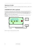
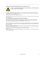
Position the remote panel in the place chosen for monitoring
Proceed to connect power supply (220-240V/50-60Hz) to the M3 connector of the PCB board, remembering to leave
the central terminal free
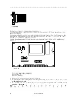
Carry out connection between interface connector indicated with the letter B (picture 20) and the M1 connector . Bear
in mind that the connection must be carried out symmetrically (pin1-pin14, pin2-pin13, . . ., pin13-pin2, pin14-pin1)
Close the U.P.S second access by fastening the screws
Continue the starting procedure (if already operative restore functioning from U.P.S by-pass following the relative
instructions)
The remote panel kit is composed by:
N 1 remote panel
N 1 interface board
1. Mount remote panel in a place designed to monitoring
2. Supplies it (220-240V/50-60Hz) from socket M3 (picture 10.2), where pin1 is the phase, and pin 3 is a
neutral, pin 2 must be void
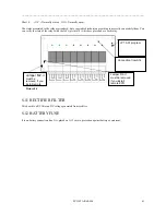
3. A14 and A16, must be connected by 14 poles wire not supplied. Corrispondance between A14 and A16
connector is as follows:
A14
1 2 3 4 5 6 7 8 9 10
11
12
13
14
A16
14
13
12
11
10 9 8 7 6 5 4 3 2 1
M1
M2
M3
1 14
Picture 10.4
Picture 10.5

