________________________________________________________________________________
EVO STAR 60-800
12
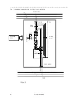
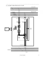
3.1.1 RECTIFIER
Rectifier indicated in picture with the abbreviation RECT, transforms alternating current voltage from main line to
direct current voltage. Its engineering allows, through a six pulse absorption to feed the inverter in its status of
maximum voltage output at the same time as the battery charge. Normally, direct current voltage is constantly set at
436Vdc (sustaining voltage), but when recharging the batteries, this voltage will be automatically limited by a current
limiter.
In the following description the link from rectifier to inverter is defined as “Dc-link” and the voltage between its
poles is defined as “Dc link voltage”
3.1.2 INVERTER
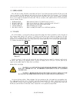
The inverter, indicated in picture 3.1 with the abbreviation INV, has the role of transforming direct current voltage,
taken from the rectifier output, into sinusoidal voltage, which may be used by the user; This process is carried out by
using power semiconductors, piloted by a PWM signal, which through a transformer and a capacitance filter give us a
very stable three-phase voltage with a harmonic distortion lower than one unit.
The controlling logic of the inverter also controls output current intensity limiting it to a value which corresponds to
150% nominal current voltage.
3.1.2 STATIC COMMUTATOR
The static commutator indicated in picture 5 as B.S., is a commutator made with semiconductors which can select
which power source to connect appliances to. During normal functioning the U.P.S. output is taken at the inverter
output (U.P.S. on-line), but if there is an internal or external event it will commute to the reserve system.
Commutating from one source to another occurs without creating voltage
“dips” only with conditions of synchronism between inverter output and the
reserve system. If there is forced commuting, without synchronism, decided by
the user, this will occur with a voltage dip of max. 20 Sm.
Commuting Conditions on inverter:
1.
Inverter switched on and working and synchronized with the
reserve system
2.
Loss of system
3.
Voluntary forcing through control panel
Commuting Conditions on reserve:
1.
Malfunctioning of the inverter
2.
Current overcharge
3.
U.P.S. switched off
4.
Voluntary forcing through control panel
Output voltage
L1 L2 L3
LN
Picture 3.3
Input voltage
To battery
To inverter
U
V
W
Picture 3.2


