________________________________________________________________________________
EVO STAR 60-800
40
8.10
RELAY BOARD
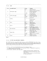
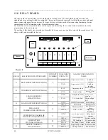
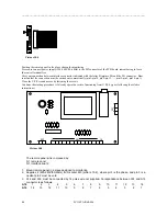
The relay board is a user interface system, which allows viewing of the U.P.S. State through eight diverters, one
standard and seven optional, which are controlled. These contacts are used especially to start up the acoustic and visual
alarm systems when specific events occur. The types of relays, which are used, allow connecting functioning electric
equipment up to 250V alternating, with a 5A maximum absorption.
For each relay we can associate an alarm or we keep the standard setting. In case of particular requirement for relay
programming, to aks our engineers.
The position of this board varies according to the model, but in any case once you have removed the second access it is
always visible and accessible to the user.
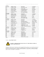
RELAY
RELATED STATE (STANDARD)
CONTACT
NUMBER
AVAILABLE
CONTACTS
ALARM CONFIGURATION
TABLE
1 N.C.
Output current > 150%
Load on
reserve
A RECTIFIER
STARTED(OPTIONAL) 2
3 N.A.
Output current > 125%
Load on
inverter
4 N.C.
Frequency alarm
Reserve frequency
KO
B INVERTER
STARTED(OPTIONAL) 5
6 N.A.
Sincro alarm
Reserve voltage
KO
7 N.C.
Zero phase alarm
Wrong reserve
phase seq.
C
LOAD ON RESERVE
LINE(OPTIONAL)
8
9 N.A.
V Inverter bad
Main voltage
KO
10 N.C.
IGBT Desaturation
Boost charge
D
LOAD ON INVERTER(OPTIONAL)
11
12 N.A.
Inverter on
Rectifier ON
13 N.C.
Summary alarm
Rec. Phase seq.
Wrong
E
PRE-ALARM
TEMPERATURE(OPTIONAL)
14
15 N.A.
VDC < 350V
High temp.
Rectifier
16 N.C.
Iout > Rating current
Relay board
jumper
F
TEMPERATURE ALARM OR
DESATURATION(OPTIONAL)
17
18 N.A.
Power supply alarm
Battery switch
19 N.C.
DC Link fault
By-pass switch
G
LOW BATTERY
VOLTAGE(OPTIONAL)
20
21 N.A.
Pre Temp. Alarm
Output switch
22 N.C.
High Temp. Alarm Reserve switch
H
OUTPUT CURRENT >
125%(OPTIONAL)
23
24 N.A.
Voltage out KO
Main switch
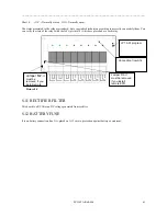
CN2
CN3
Led
Jumper
1
24
A
B
C
D
E
F
G
H
Terminal
CN1
Picture 18

