________________________________________________________________________________
EVO STAR 60-800
28
7
CONTROL PANNEL
The user can communicate with the U.P.S. in the following ways:
1.
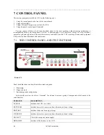
Using the control panel on the front of the control board
2.
Using relay interface
3.
Using a Personal Computer connected to the U.P.S.
4.
Using the remote control panel (Optional)
You can connect all these check tools described above to the same machine without creating interference or
incompatibility among the components. The use of photocouplers on all interfaces (except for relay interface)
guarantees galvanic separation of the interfaces remote controlled from the U.P.S. assuring all connected equipment
total protection from disturbance and interference.
7.1
THE CONTROL PANEL AND ITS FUNCTIONS
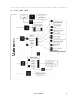
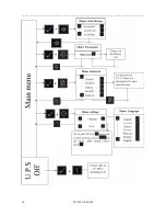
Panel check functions can be split into three main categories:
1.
Monitoring
2.
Diagnostic tools
3.
Functioning mode configuration
In the interface system we refer to “elements”. For element we mean a group of components which concur to the
same function.
ELEMENTS DESCRIPTION
SYSTEM
Includes the U.P.S. as a whole
RECTIFIER
Includes devices for conversion from alternating to direct voltage
BATTERY
Includes the device for energy storage
INVERTER
Includes devices for conversion from alternating to direct voltage
BACK-UP
This is the emergency mains supply
BREAKERS
Includes all the breakers in the U.P.S.
Picture 7.1


