________________________________________________________________________________
EVO STAR 60-800
19
loads or loads with strong harmonic distortion. Taking into account these last remarks, the enlargement factor must be
decided according to the size of the phase wire (usually 1,5-2 times).
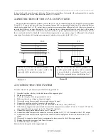
4.4 PROTECTION OF THE U.P.S. OUTPUT LINE
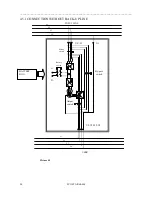
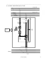
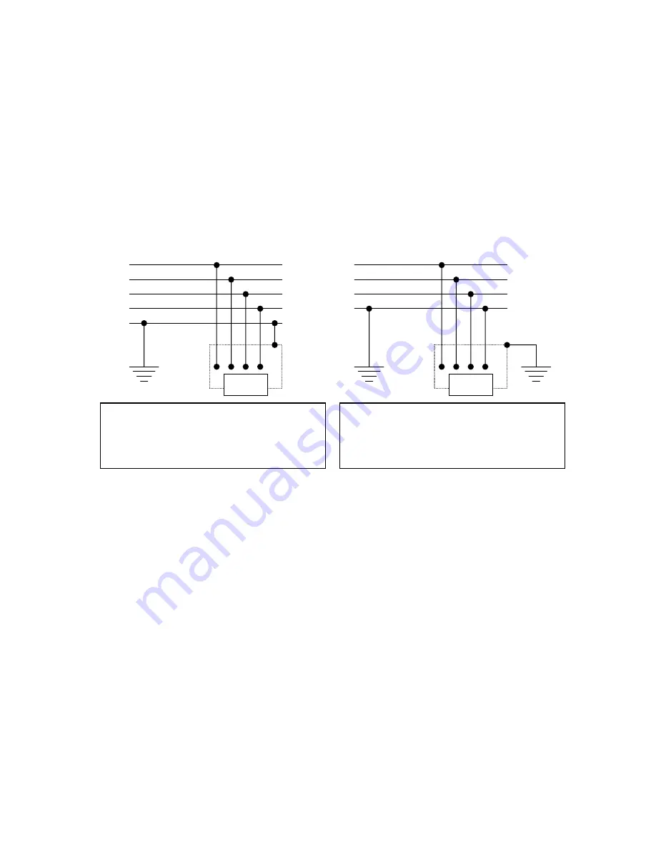
The main electric distribution systems to which the U.P.S. can be connected are the TN-S and TT systems (pictures
4.1 and 4.2). If you do not have this type of equipment please talk to a specialized technician. The protection devices,
which can be applied to the U.P.S. output line, are against overcurrent and are differential. As for their size, please bear
in mind that if there is a power shortage the U.P.S. works on its own (disconnected from the main line), with a current
restriction equal to 150% of the rated current, therefore in order to protect against overcurrent you must choose a device
that is activated within this threshold. As for differential protections you must use type A differentials (for alternate
current and for switches with continuous components), which are low sensitivity (0,3–0,5-1 A).
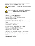
4.5 CONNECTING THE SYSTEM
To connect the U.P.S. you must carry out the following procedures:
1.
Open the front door, the key is attached to one of the supporting feet
2.
Shutdown all breakers.
3.
Verify the integrity of the by-pass breaker lock out
4.
Make sure there is no voltage on the mains supply
5.
Unscrew the second access panel setscrews and remove the panel
6.
Connect the earthling wire for the mains to the earth bar
7.
Connect the general mains to the U, V and W terminals of the U.P.S. ( in cyclic sense)
8.
If the back-up supply mains are available disconnect the jumpers from terminals U1 and U, V1 and V, W1 and W,
then connect the back-up supply to the U1, V1 and W1 terminals
9.
Connect the supply mains neutral wire to the N1 terminal
10.
Connect the mains that power the connected electric equipment to U2, V2 e W2 terminals at the U.P.S. output
11.
Connect the mains neutral wire that powers the connected electric equipment to the N2 terminal at the U.P.S.
output
12.
If you need to connect external battery compartments please proceed to the following paragraph.
13.
Replace the second access panel and fasten its screws.
14.
Lock the front door with its key
Reassemble the side grids on the supporting base
N
PE
TN-S
L1
L2
L3
N
PEN
U.P.S
The TN-S system has the neutral grounded in a
specific point to which the system’s earth is also
connected with a separate protection wire.
TT
L1
L2
L3
N
U.P.S
The TT system has the neutral grounded in a
specific point and the system’s earth is connected
to an earth which is independent from the neutral.
This is the most used device at distribution level.
Picture 4.1
Picture 4.2


