________________________________________________________________________________
EVO STAR 60-800
39
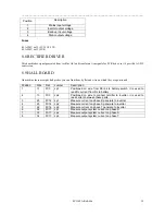
Position
Description
1
Mains input voltage
2
Inverter output voltage
3
Back-up input voltage
4
Static output voltage
Fuses
0.5A 250V 6x32 (FU1 FU2 FU3)
0.2A 250V 6x32 (FU4)
8.8 RECTIFIER DRIVER
This board takes signal generated from rectifier A03 and transforms it in signals for SCR driver, so it’s possible AC-DC
conversion.
8.9 HALL BOARD
On machine there are eight hall probes, you can find them by flat and wire on which they are positioned
Position Wire
Flat Jumper Description
1
13
FC3
Jp1
Positioned on wire from DClink to battery switch, it is used to
read Dc current from Dc to battery
2
13
FC3
Jp2
Positioned on wire to connect retcifier to inverter, it is used to
read current between these parts
3
20
FC14 Jp1
Measure current on phase R generate to inverter
4
23
FC14 Jp2
Measure current on phase S generate to inverter
5
26
FC14 Jp3
Measure current on phase T generate to inverter
6
32
FC17 Jp1
Measure output system current on phase R
7
33
FC17 Jp2
Measure output system current on phase S
8 34
FC17
Jp3
Measure
output
system current on phase T

