________________________________________________________________________________
EVO STAR 60-800
17
3.1.8
TERMINAL CONNECTORS
POWER UP TO 150 KVA
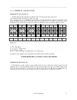
In all the models the terminal board is on the front of the U.P.S. protected by the second access.
It can be perpendicular or horizontal according to the model.
In any case, please refer to the alphanumeric specifications on the terminal board. The jumpers are arranged as in the
picture (highlighted in grey), and are used to short-circuit the main input and the reserve input. According to the type of
installation, you can remove them to connect the system to an auxiliary power source (back-up supply, generator).
U, V, W = Main input
U1, V1, W1, N1 = Reserve input
U2, V2, W2, N2 = Output
D(-),C(+) = Battery pole input. D(-) negative pole, C(+) positive pole.
In 100KVA device terminal D and C are double, in 120-150KVA also N1 and N2 are double
In this manual fase name U, V, W or R, S, T, or R, Y, B are equivalent
.
POWER OVER 150 KVA
In the high power systems instead of using terminal boards for power connections a group of copper bars with
perforated ends are used. Therefore with the help of cable terminals, knurled screws and nuts a suitable connection for
the current values in circulation. As for the connection references please refer to the alphanumeric specifications on the
copper bars which respect the same specifications present on the terminal boards in equipment up to 200KVA.
U
U1
V
V1
W
W1
N1
U2
V2
W2
N2
D(-)
C(+)
Picture 3.8


