4. INSTALLATION PROCEDURE FOR OPTIONAL EQUIPMENT
EO18-33012A
4.3 STRIP MODULE (B-9904-H-QM)
4-15
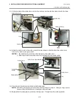
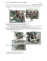
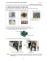
13) Secure the strip sensor (LED) and strip sensor (Tr) to the printer with the SM-4x8B screws.
14) Connect the shorter harness of the strip sensor (Tr) to the strip sensor harness (for LED).
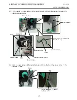
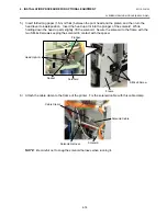
15) Fix the connected strip sensor harness (for LED) to the base with the cable clamp. While passing
the other strip sensor harness through the cut and the bush, reassemble the operation panel ass’y
to the printer. Then pass the strip sensor harness over the tab on the back of the operation panel
ass’y.
NOTE:
Be careful not to pinch the strip sensor harnesses by the operation panel.
SM-4x8B Screw
Strip Sensor
(Tr)
Strip Sensor
Harness (for LED)
Shorter Harness of the Strip
Sensor Harness (for Tr)
Strip Sensor (LED)
SM-4x8B Screw
Tab
Strip Sensor (Tr)
Bush
Strip Sensor Harness (for LED)
Cable Clamp
Operation
Panel Ass’y
Strip Sensor Harness
Cut
Summary of Contents for B-SX4T Series
Page 3: ...TEC Thermal Printer B SX4T QQ QP Owner s Manual ...
Page 54: ......
Page 56: ......
Page 57: ......
Page 58: ...M EO1 33034 ...
Page 59: ...TEC Thermal Printer B SX5T QQ QP Owner s Manual ...
Page 112: ......
Page 114: ......
Page 115: ......
Page 116: ...M EO1 33036 ...
Page 141: ......
Page 142: ...PRINTED IN JAPAN EO10 33013A ...
Page 312: ......
Page 313: ......
Page 314: ...PRINTED IN JAPAN EO18 33012A ...
Page 315: ......
Page 316: ...PRINTED IN JAPAN EO0 33013A ...


