background image

4.2.3

4.2.3

4.2.3

4.2.3


Navigating the Menu System Using the Shortcut Keys

Navigating the Menu System Using the Shortcut Keys

Navigating the Menu System Using the Shortcut Keys

Navigating the Menu System Using the Shortcut Keys    

The menu structure can also be navigated using shortcut keys.  This greatly reduces the number of key pressed required 
to gain access to the menu items and therefore reduces the system programming time.  The feature works by pressing the 
numeric keys that correspond to menu options.   
 
For example, to view the Software Version of the SOLOgarde controller: 


The first item in the menu is the ACU

ACU

ACU

ACU option (the one that is highlighted).  This is option 1 and if by 

pressing the numeric key 1

1

1

1, it will be selected.   


The programmer now presents the options in the ACU

ACU

ACU

ACU menu.  System Information (Sys info

Sys info

Sys info

Sys info) is the 5

th


option in the menu system so if key 5

5

5

5 is now pressed, the System Information menu will be selected. 


Finally to display the software version, the Version

Version

Version

Version menu option would need to be selected, which is the 

5

th

 option in the menu.  Select it by pressing key 5

5

5

5.   

 
So from logging in to displaying the software version simply press the keys 1

1

1

1, 5

5

5

5, 5

5

5

5 in sequence and the Version

Version

Version

Version menu is 

accessed in just three key presses. 
 
Use the #

#

#

# key to escape out of menus or delete entries as necessary, referring to section 4.2.1 of this manual. 

 
Appendix A shows the full menu structure together with the numeric keys that correspond to each menu option. 

4.3

4.3

4.3

4.3


Switching Off

Switching Off

Switching Off

Switching Off    the SOLOgarde Hand

the SOLOgarde Hand

the SOLOgarde Hand

the SOLOgarde Hand----Held Programmer and Disconnecting

Held Programmer and Disconnecting

Held Programmer and Disconnecting

Held Programmer and Disconnecting    

The SOLOgarde hand-held programmer will shut down automatically after 5 minutes of inactivity to conserve battery 
power.  This will occur regardless of whether the programmer is connected to the SOLOgarde reader or not. 


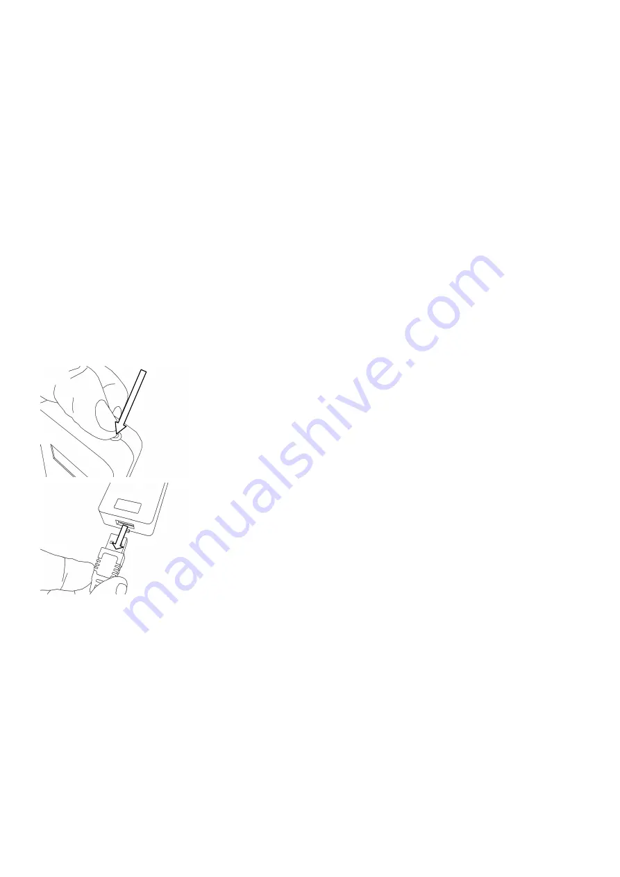
Turn the programmer off by pressing and holding the power button at the top of 
the unit until the display goes blank.  The unit is now switched off. 


Disconnect the SOLOgarde hand-held programmer from the reader by gently 
pulling on the plug housing. 
 

Note: do not pull on the lead ot

Note: do not pull on the lead ot

Note: do not pull on the lead ot

Note: do not pull on the lead otherwise it may become damaged.

herwise it may become damaged.

herwise it may become damaged.

herwise it may become damaged.    

    
Should the programmer be disconnected from the SOLOgarde reader before it has been switched off, the programmer will 
automatically log out of the controller and the Connect

Connect

Connect

Connect screen will be displayed. 

Summary of Contents for SOLOgarde

Page 1: ...m To Register your Product To Register your Product To Register your Product To Register your Product Visit http www tdsi Visit http www tdsi Visit http www tdsi Visit http www tdsi product product pr...

Page 2: ......

Page 3: ...it to marketing tdsi co uk User User User User Manual Improvement Form Manual Improvement Form Manual Improvement Form Manual Improvement Form Manual Manual Manual Manual UM0028 Issue Issue Issue Iss...

Page 4: ......

Page 5: ...pyright Notice Copyright Notice Copyright Notice Copyright Notice Copyright 2008 Time and Data Systems International Ltd TDSi This document or any software supplied with it may not be used for any pur...

Page 6: ...u System using the Shortcut Keys 29 4 2 3 Navigating the Menu System Using the Shortcut Keys 30 4 3 Switching Off the SOLOgarde Hand Held Programmer and Disconnecting 30 5 Programming SOLOgarde 31 5 1...

Page 7: ...l Unit SOLOgarde Control Unit Figure Figure Figure Figure 2 2 2 2 SOLOgarde Control Unit Terminal Label Removed SOLOgarde Control Unit Terminal Label Removed SOLOgarde Control Unit Terminal Label Remo...

Page 8: ...nstallation Preparing the Controller for Installation Preparing the Controller for Installation The controller is supplied ready for installation Remove all packaging and check the contents of the kit...

Page 9: ...k or side of the box When mounting in the Wall Mounting Box with USB Connector pass the cables through the back or side of the box and connect any reader screen braids to the earth terminal Now go to...

Page 10: ...door sense is being used then leave the Sense Sense Sense Sense link off For positive alarm action i e the Alarm output is to be taken to 12 V during an alarm condition fit a jumper to the link marked...

Page 11: ...ock marked Reader 1 Reader 1 Reader 1 Reader 1 as shown opposite If two readers are to be installed this is the reader that controls access from the unsecure area to the secure area Note that the cabl...

Page 12: ...Reader 2 Reader 2 Reader 2 Reader 2 as shown opposite If two readers are to be installed this is the reader that controls access from the secure area to the unsecure area Note that the cable colours...

Page 13: ...nent irreparable damage t permanent irreparable damage t permanent irreparable damage to the o the o the o the controller controller controller controller Figure Figure Figure Figure 10 10 10 10 Wirin...

Page 14: ...mper Switch Wiring a Tamper Switch Tamper Tamper Tamper Tamper If a tamper switch is to be fitted connect this between the Tamper Tamper Tamper Tamper and Common Common Common Common terminals Figure...

Page 15: ...hat the door is not open The alarm will automatically silence after a period of 30 seconds Alternatively use the hand held programmer to reset the alarm refer to section 3 4 6 of this manual for detai...

Page 16: ...by offer the SOLOgarde controller into the box face down Remove the backing from the foam spacers and stick these to the rear of the cover so that the fixing screws will pass through the centre of th...

Page 17: ...r date Please use the Record Sheet supplied e Please use the Record Sheet supplied e Please use the Record Sheet supplied e Please use the Record Sheet supplied with the cards to ensure with the cards...

Page 18: ...ce Replace being displayed To overwrite the card information with the new data that is to be entered use the key to highlight OK OK OK OK and press the key to replace the card To abort the process hig...

Page 19: ...the options have been set it is time to validate the card Ensure that the Validate Validate Validate Validate option is highlighted flashing and press the key Confirm the entry by pressing the key onc...

Page 20: ...hat is to be entered use the key to highlight OK OK OK OK and press the key to replace the card To abort the process highlight Esc Esc Esc Esc and press the key Hint it is not necessary enter the full...

Page 21: ...n set it is time to validate the card Ensure that the Validate Validate Validate Validate option is highlighted flashing and press the key Confirm the entry by pressing the key once again The controll...

Page 22: ...layed You are then prompted to enter a valid card number Hint it is not necessary enter the full number for example for the card numb Hint it is not necessary enter the full number for example for the...

Page 23: ...ly useful for temporarily unlocking a door for example a meeting room or lecture theatre or setting unsetting of an intruder panel Use the or keys to highlight your required card Type Type Type Type a...

Page 24: ...1 Crd Code Crd Code Crd Code Crd Code where the user is required to present their card followed by a global code using the reader keypad 1 Use the or keys to highlight your required card Mode Mode Mod...

Page 25: ...e Delete Delete option is highlighted flashing and press the key to select it With the Single Single Single Single option selected press the key to select Either enter the card number to be deleted us...

Page 26: ...ed to JP2 JP2 JP2 JP2 the alarm output will be activated and the green Alarm Alarm Alarm Alarm LED will be illuminated Additionally the red LED on the reader will flash at an increased rate This will...

Page 27: ...de will also signal an alarm condition if the input voltage is out of range This will continue until the voltage returns to its normal level and the alarm is reset using the hand held programmer 3 4 6...

Page 28: ...r and the equipment to which is connected damage could result to both the programmer and the equipment to which is connected 4 1 4 1 4 1 4 1 Preparing the SOLOgarde Hand Preparing the SOLOgarde Hand P...

Page 29: ...tion with the accept key and the escape or delete key While in the menu system one of the options will be flashing This is the one that is currently highlighted and by pressing the key this option wil...

Page 30: ...sion Version Version menu is accessed in just three key presses Use the key to escape out of menus or delete entries as necessary referring to section 4 2 1 of this manual Appendix A shows the full me...

Page 31: ...t Silent Silent mode i e to disable the on board sounder press the key to highlight Enable Enable Enable Enable and press the key to accept the selection If it is necessary to switch the on board soun...

Page 32: ...necessary to reset it using the hardware link Please refer to section necessary to reset it using the hardware link Please refer to section 5 1 4 1 5 1 4 1 5 1 4 1 5 1 4 1 of this manual on how to do...

Page 33: ...and log in to the controller by entering the 4 digit password followed by the button For more details on logging in and the password feature please refer to section 4 2 of this manual Ensure that the...

Page 34: ...s Value A 9 1 V to 14 9 V Value B 4 9 V to 5 1 V The Memory Memory Memory Memory screen shows the amount of memory that has been used within the controller Card Card Card Card shows the number of card...

Page 35: ...roller was found to be out of range 3 The on board regulated supply voltage was found to be out of range 4 An alarm condition has occurred 5 An error was found in the memory of the controller 6 An iss...

Page 36: ...ssword 4 Reset 5 System Information 6 Diagnostics 1 Disable 2 Enable 1 Alarm 2 ACU 1 Input Output Status 2 Voltage 3 Memory 4 UID 5 Software Version 6 Master Card 1 Test 2 Clear 1 Add 2 Edit 3 Delete...

Page 37: ...er too quickly Present the card to the reader for a longer period of time Input supply voltage is too high This may be accompanied by an alarm condition from the controller Reduce the supply voltage t...

Reviews: