

83-530-000 Rev. G
69
CAUTION
When the Isolated Analog Option is installed, do not apply any signals to the
non-isolated VPGM and IPGM (J1-9 and J1-10) pins. All other J1 features may
be used normally. Refer to Section 4.5 for a description of J1 features.
CAUTION
To prevent damage to the unit, do not program the output voltage and
current to higher then the power supply rating.
NOTE
J1-8 and J1-12 must be shorted together with a jumper.
NOTE
J1-8 and J1-12 must be shorted together with a jumper.
NOTE
SW1 position 3 and 4 must be in their Up position for operation
with 4-20mA Isolated Programming and Monitoring.
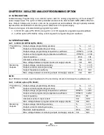
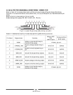
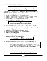
8.4 SETUP AND OPERATING INSTRUCTIONS
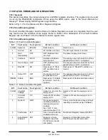
8.4.1 Setting up the power supply for 0-5/0-10V Isolated Programming and Monitoring
Perform the following procedure to configure the power supply.
1. Turn the power supply AC power switch to Off.
2. Connect a short between J1-8 and J1-12 (refer to Table 4-4).
3. Set the Setup switch SW1 positions 1 and 2 to their Up position.
4. Set SW1 position 3 to select the programming voltage range: Down=0-5V, Up=0-10V.
5. Set SW1 position 4 to select the monitoring range: Down=0-5V, Up=0-10V.
6. Ensure that SW1 positions 7 and 8 are in their down position.
7. Connect the programming sources to the mating plug of the Isolated Programming connector. Ob-
serve for correct polarity of the voltage source.
8. Set the programming sources to the desired levels and turn the power supply ON.
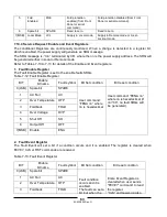
8.4.2 Setting up the power supply for 4-20mA Isolated Programming and Monitoring
Perform the following procedure to configure the power supply:
1. Turn the power supply AC power switch to Off.
2. Connect a short between J1-8 and J1-12 (refer to Table 4-4).
3. Set the Setup switch SW1 positions 1 and 2 to their Up position.
4. Set SW1 position 3 to its Up position.
5. Set SW1 position 4 to its Up position.
6. Ensure that SW1 positions 1 and 2 to their Up position.
7. Connect the programming source to the mating plug of the Isolated Programming connector.
Observe for correct polarity of the voltage source.
8. Set the programming sources to the desired levels and turn the power supply ON.
Summary of Contents for GENESYS 10KW
Page 2: ......
Page 3: ......
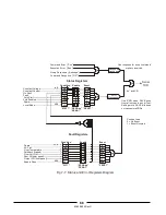
Page 31: ...83 530 000 Rev G 28 Fig 4 2 Rear panel connections and controls...


