


83-530-000 Rev. G
11
5. DYNAMIC CHARACTERISTICS
V
7.5
10
12.5
20
25
30
40
50
60
80
100
125
150
200
250
300
400
500
600
1. Up-prog. response time, 0~Vomax full-
load
mS
100
100
100
100
100
100
100
100
100
100
100
100
100
100
100
100
100
100
100
2. Down-prog response time full-load
mS
100
100
100
100
100
100
100
100
100
100
100
100
100
100
100
100
100
100
100
3. Transient response time (cv mode)
mS
Note:
4. Time for Ouput Stable
S
5. Output fall and rise
---
6.Start-up delay
S
Less than 7 (without IEEE option)
6. REMOTE ANALOG CONTROL AND SIGNALS
1. Vout voltage programming
---
0~100%, 0~5V or 0~10V, user selectable. Accuracy & Lin/-1% of Rated Vo.
2. Iout voltage programming
---
0~100%, 0~5V or 0~10V, user selectable. Accuracy & Lin/-1% of Rated Io.
3. Vout resistor programming
---
0~100%, 0~5/10kohm full scale, user selectable. Accuracy & Lin/-1% of Rated Vo.
4. Iout resistor programming
---
0~100%, 0~5/10kohm full scale, user selectable. Accuracy & Lin/-1% of Rated Io.
5. On/Off control (rear panel)
---
6. Output current monitor
---
0~5V or 0~10V , accuracy:1% , user selectable
7. Output voltage monitor
---
0~5V or 0~10V , accuracy:1% , user selectable
8. Power supply OK signal
---
Yes. TTL high-OK, 0V (500ohm impedance)-Fail
9. Parallel operation
---
available on digital interface and displayed on front panel of Master unit.
10. Series operation
---
Possible (with external diodes) , up to identical 2 units with total output not to /-600V from chassis ground.
11. CV/CC signal
---
CV: TTL high (4~5V) source: 10mA, CC: TTL low (0~04V):10mA
12. Enable/Disable
---
13. Remote/Local selection
---
14. Remote/Local signal
---
Signals operating mode in use.
7.FRONT PANEL
1. Control functions
---
Vout/ Iout manual adjust by separate encoders
---
OVP/UVL manual adjust by Volt. Adjust encoder
---
---
---
---
---
Foldback control (CV to CC)
---
RS232/485 and IEEE488.2 selection by IEEE or LAN enable switch and DIP switch
---
---
Re-start modes (auto , safe)
---
Front Panel Lock/Unlock
---
S = Slave
2. Display
---
Vout: 4 digits , accuracy: 0.5% of rated Vout+/-1count , Green LED's , Size:10mm
---
Iout:
4 digits , accuracy: 0.5% of rated Iout+/-1count , Green LED's , Size:10mm
3. Indications
---
CC/CV : GREEN LED's. ALRM (OVP,OTP,FOLD,AC FAIL): RED LED
Properties 5.1-5.6 with Resistive Load.
2 maximum from enable output until output stable.
rated output set-point: less than 3.
Address selection by Voltage adjust encoder. No of addresses:31
AC On/Off
Overshoot limited to 125% Rated Output. Voltage at No-Load, Full-Load, Resistive load.
H3 = One Master, Two Slaves H4 = One Master, Three Slaves,
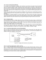
Up to Four (4) identical units may be connected in Master/Slave Mode with 'Single' wire connection.
In Advanced parallel feature, the current of Master Unit, multiplied by number of units connected in parallel, is made
Remote analog current monitor of the Master is scaled to output current of the Master unit (only).
Go to Local
Dry contact. Open:off , Short: on. Max. voltage at Enable/Disable Contacts 6V
Selects Remote or Local operation by elect. Voltage: 0~0.6V/2~15V, <0.6V = Local 2-15V = Remote
Voltmeter is user selectable to read either local voltage (at power supply) or remote voltage (at the load).
Baud rate selection by Current adjust encoder.
Output On/Off
Parallel Master Slave: H1 = One Master, Zero Slave, H2 One Master, One Slave
ADDR., OVP/UVL , V/A , FOLD, REM./LOCAL, OUT ON/OFF, LFP/UFP, IEEE, LAN, Hx (Parallel Master) or S (Slave).
Time for the output voltage to recover within 2% of its rated output voltage for a load change of 50~100% or 100~50% of
By Voltage: 0.6V = Disable, 2-15V = enable (default) or dry contact, user selectable logic
Summary of Contents for GENESYS 10KW
Page 2: ......
Page 3: ......
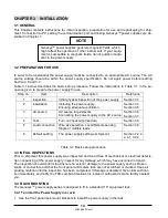
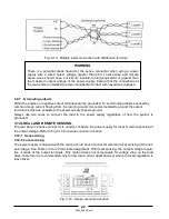
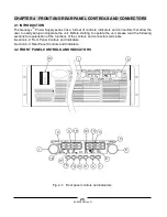
Page 31: ...83 530 000 Rev G 28 Fig 4 2 Rear panel connections and controls...


