


83-530-000 Rev G
22
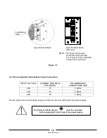
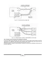
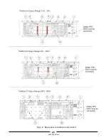
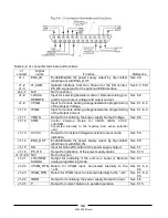
Fig. 3-13: Multiple loads connection with distribution terminal
3.9.7
Grounding outputs
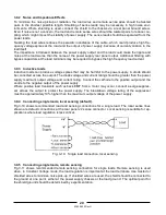
Either the positive or negative output terminals can be grounded. To avoid noise probems caused by
common-mode current flowing from the load to ground, it is recommended to ground the output
terminal as close as possible to the power supply chassis ground.
Always use two wires to connect the load to the power supply regardless of how the system is
grounded.
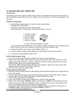
3.10 LOCAL AND REMOTE SENSING
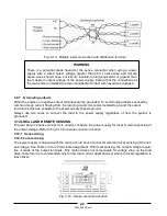
The rear panel J2 sense connector is used to configure the power supply for local or remote sensing of
the output voltage. Refer to Fig.3-14 for sense connector location.
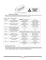
3.10.1 Sense wiring
3.10.2 Local sensing
The power supply is shipped with the rear panel J2 sense connector wired for local sensing of the out-
put voltage. See Table 3-4 for J2 terminals assignment. With local sensing, the output voltage regula-
tion is made at the output terminals. This method does not compensate for voltage drop on the load
wires, therefore it is recommended only for low load current applications or where the load regulation is
less critical.
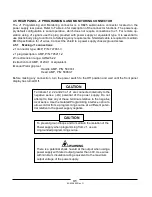
Fig. 3-14: Sense connector location
WARNING
There is a potential shock hazard at the sense connector when using a power
supply with a rated output voltage greater than 40V. Local sense and remote
sense wires should have a minimum insulation rating equivalent or greater than
the maximum output voltage of the power supply. Ensure that the connections at
the load end are shielded to prevent accidental contact with hazardous voltages.
1
5
2 3 4
+S +LS
NC
-LS -S
Summary of Contents for GENESYS 10KW
Page 2: ......
Page 3: ......
Page 31: ...83 530 000 Rev G 28 Fig 4 2 Rear panel connections and controls...


