


83-530-000 Rev. G
23
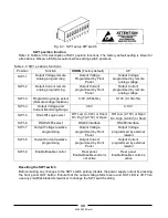
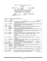
Terminal
Function
J2-1
Remote positive sense (+S)
J2-2
Local positive sense. Connected internally to the positive output terminal (+LS).
J2-3
Not connected (NC)
J2-4
Local negative sense. Connected internally to the negative output terminal (-LS).
J2-5
Remote negative sense (-S).
Table 3-4: J2 terminals
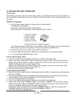
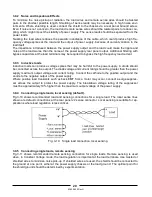
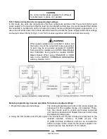
3.10.3 Remote sensing
Use remote sense where the load regulation at the load end is critical. In remote sense, the power sup-
ply will compensate for voltage drop on the load wires. Refer to the power supply specifications for the
maximum voltage drop on load wires. The voltage drop is subtracted from the total voltage available at
the output. Follow the instructions below to configure the power supply for remote sensing:
1. Ensure that the AC On/Off is in the Off position.
2. Remove the local sense jumpers from J2.
3. Connect the negative sense lead to terminal J2-5 (S) and the positive sense lead to terminal J2-
1(+S) of the J2 mating connector. Ensure that the J2 mating connector is plugged securely into the
rear panel sense connector, J2.
4. Turn On the power supply.
Notes:
1. If the power supply is operating in remote sense and either the positive or negative load wire is not
connected, an internal protection circuit will activate and shut down the power supply. To resume
operation, turn the to the Off position, connect the open load wire, and turn On the power supply.
2. If the power supply is operated without the remote sense lines or local sense jumpers, it will con-
tinue to work, but the output voltage regulation will be degraded. Also, the OVP circuit may activate
and shut down the power supply.
3.10.4 J2 sense connector technical information
-
J2 connector type: MC 1.5/5-G-3.81, Phoenix.
-
Plug type: MC 1.5/5-ST-3.81, Phoenix.
-
Wire AWG; 28 up to 16.
-
Stripping length: 7mm (0.28 inches).
-
Tightening torque: 0.22-0.25Nm (1.95-2.21Lb-Inch.)
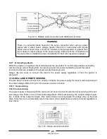
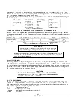
WARNING
There is a potential shock hazard at the sense point when using power supply
with a rated output voltage greater than 40V. Ensure that the connections at the
load end are shielded to prevent accidental contact with hazardous voltages.
CAUTION
When using shielded sense wires, ground the shield
in one place only. The location can be the power sup-
ply chassis or one of the output terminals.
Summary of Contents for GENESYS 10KW
Page 2: ......
Page 3: ......
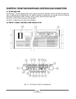
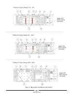
Page 31: ...83 530 000 Rev G 28 Fig 4 2 Rear panel connections and controls...


