


83-530-000 Rev G
52
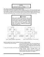
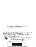
NOTE
The address (ADR n) command must return an “OK” response
before any other commands are accepted.
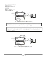
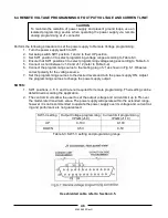
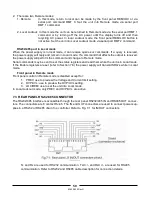
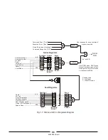
Multi power supply connection to RS232 or RS485 bus
Up to 31 units can be connected to RS232 or RS485 bus. The first unit connects to the controller via
RS232 or RS485 and the other units are connected with RS485 bus.
1. First unit connection: Refer to Section 7.4.1 for connecting the first unit to the controller.
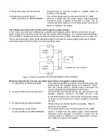
2. Other units connection: The other units on the bus are connected via their RS485 interface.
Refer to Figure 7-5 for typical connection.
- Set rear panel setup switch SW1-6 to its UP position.
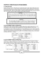
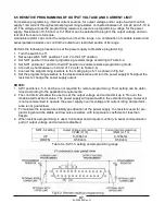
- Using the Linking cable (refer to Fig. 7-6), connect each unit OUT connector to the next unit IN
connector.
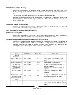
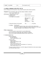
7.5 COMMUNICATION INTERFACE PROTOCOL
IN
OUT
POWER SUPPLY
#1
IN
OUT
POWER SUPPLY
#2
IN
OUT
POWER SUPPLY
#3
IN
OUT
POWER SUPPLY
#31
RS232/RS485
RS485
RS485
RS485
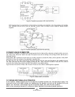
Fig7-5: Multiple power supply RS232/485 connection
8
1
1
8
1
6
3
5
4
1
6
3
5
4
PIN NO.
HOUSING
HOUSING
PIN NO.
NAME
NAME
SHIELD
SG
TXD
TXD
RXD
RXD
SHIELD
SG
RXD
RXD
TXD
TXD
-
+
+
+
+
-
-
-
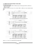
Serial link cable with RJ-45 shielded connectors (P/N: GEN/RJ-45)
Fig.7-6:
L=0.5m typ.
Summary of Contents for GENESYS 10KW
Page 2: ......
Page 3: ......
Page 31: ...83 530 000 Rev G 28 Fig 4 2 Rear panel connections and controls...


