


83-530-000 Rev G
48
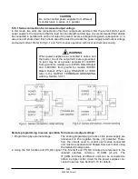
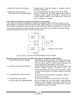
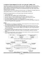
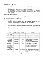
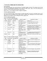
6.6 REMOTE MONITORING OF OUTPUT VOLTAGE AND CURRENT
The J1 connector, located on the rear panel provides analog signals for monitoring the output voltage
and output current. Selection of the voltage range between 0-5V or 0-10V is made by setup switch
SW1-4. The monitoring signals represent 0 to 100% of the power supply output voltage and output cur-
rent. The monitor outputs have 500 ohm series output resistance. Ensure that the sensing circuit has
an input resistance of greater than 500 Kohm or accuracy will be reduced.
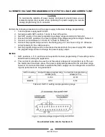
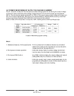
Refer to Table 6-5 for required J1 connection, SW1-4 setting and monitoring voltage range.
J1 connection
Signal
name
Signal function
Signal (+)
Return (-)
Range
SW1-4
VMON
Vout monitor
J1-11
IMON
Iout monitor
J1-24
J1-12
0-5V
Down
VMON
Vout monitor
J1-11
IMON
Iout monitor
J1-24
J1-12
0-10V
Up
Table 6-5 Monitoring signals setting
Notes:
1. Radiated emissions, FCC requirements: FCC requirements for radiated emissions use shielded
cable for the analog control signals and connect shield to
chassis (As stud is provided near J1).
2. Front panel encoders operation:
In Remote analog mode the output voltage and current
can’t be set by the VOLTAGE and CURRENT encoders.
3. Front panel PREV button:
Use PREV button to display the output voltage and current
setting defined by the encoders or communication.
4. Communication:
In Remote analog mode, power supply parameters can be
programmed and readback via the communication port ex-
cept output voltage and current setting.
Summary of Contents for GENESYS 10KW
Page 2: ......
Page 3: ......
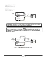
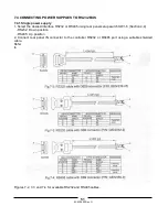
Page 31: ...83 530 000 Rev G 28 Fig 4 2 Rear panel connections and controls...


