


83-530-000 Rev. G
13
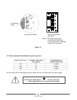
1. 208 Volts Input Models
1. ESD
---
2. Fast transients
---
3. Surge immunity
---
4. Conducted immunity
---
5. Radiated immunity
---
6. Power Frequency Magnetic Field
7. Conducted emission
---
8. Radiated emission
---
2. 400 Volts Input Models
CE Mark
1. ESD
---
2. Fast transients
---
3. Surge immunity
---
4. Conducted immunity
---
5. Radiated immunity
---
6. Power Frequency Magnetic Field
---
7. Voltage Dips, Short Interruptions and
---
Voltage Variations Immunity Tests
(400VAC Input Only)
8. Conducted emission
---
9. Radiated emission
---
CE Mark
EN55011A, FCC part 15J-A
EN61000-4-5 (IEC 1000-4-5)
EN61000-4-8
IEC 61000-4-11
EN61000-4-8
EN61000-4-6 (IEC 1000-4-6)
EN61000-4-2 (IEC 801-2) Air-disch.+/-8kV , contact disch.+/-4kV
EN61000-4-4 (IEC 1000-4-3)
EN61000-4-3 (IEC 1000-4-3)
EN55011A, FCC part 15J-A
EN61000-4-2 (IEC 801-2) Air-disch.+/-8kV , contact disch.+/-4kV
EN55011A, FCC part 15J-A
12. EMC
EN61000-4-4 (IEC 1000-4-3)
EN55011A, FCC part 15J-A
EN61000-4-5 (IEC 1000-4-5)
EN61000-4-6 (IEC 1000-4-6)
EN61000-4-3 (IEC 1000-4-3)
13 . R ELIA BILITY SPEC S
1 . Elec trolytic ca pa citor s life
Yrs.
M ore th an 3 yrs at 4 0C amb ient , 1 00% loa d
2 . Gr ad e
---
4 . W a rranty
Yrs.
5 yea rs
5 . She lf life
Yrs.
1 . ap plic able stan dards
---
2 . Insulation resistance
---
100 M oh m at 5 00 Vd c
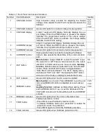
J1 -1
EN A_ IN
Ena ble/D is a ble D ry C onta ct with J1-1 4
J1 -2
IF_ CO M
Iso lated Interface C om m on . Re tu rn fo r SO, PS_ OK
J1 -3
IF_ CO M
Iso lated Interface C om m on . Re tu rn fo r SO, PS_ OK
J1 -4
N/C
J1 -5
N/C
J1 -6
N/C
J1 -7
N/C
J1 -8
LOC /R EM
Inpu t for se lectin g be tw ee n Loca l o r Re m o te a na lo g prog ram m in g
J1 -9
VPG M
Inpu t for re m ote an alo g vo lta ge/resistan ce pr ogr am m ing o f the O utpu t Voltag e
J1 -1 0
IPGM
Inpu t for re m ote an alo g vo lta ge/resistan ce pr ogr am m ing o f the O utpu t C urre nt
J1 -1 1
VM ON
Ou tp ut Vo lta ge M o nitor
J1 -1 2
CO M
C ontr ol Co mm o n for VM O N & IM O N
J1 -1 3
CV/CC
Ou tp ut fo r C onstan t Voltag e/ C on sta nt C u rr ent mod e ind ica tio n
J1 -1 4
EN A_ OU T
Ena ble/D is a ble D ry C onta ct with J1-1
J1 -1 5
SO
Inpu t for Sh ut-O ff con trol of the ou tput.
J1 -1 6
PS_ OK
Ou tp ut fo r ind ica tio n of th e po we r supp ly status
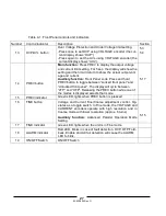
J1 -1 7
N/C
J1 -1 8
N/C
J1 -1 9
N/C
J1 -2 0
N/C
J1 -2 1
LOC /R EM Signal
Ou tp ut fo r ind ica tin g if the u nit is in Lo ca l o r R em o te a na log pr og ra m m in g m o de.
J1 -2 2
VPG M _R TN
R etur n fo r VPGM J1-9; c on nected to N eg O utput
J1 -2 3
IPGM _R TN
R etur n fo r IPGM J1-1 0; con ne cted to N eg O utpu t
J1 -2 4
IM ON
Ou tp ut fo r C urren t M o nitor
J1 -2 5
P
Ou tp ut fo r C urren t Bala nce in Par allel Op er ation (O ne w ire - Re fe re nce to Ne ga tiv e Ou tp ut)
14 . SAFETY
G-2 , La m bd a Gr ou p de rating cr ite ria & EIAJ RC R-91 02A
15 . J 1 Con nec tor
co unt Re liabililty, G en eric FaIlur e ra te s , 25 C
UL /U LC 609 50 -1, EN6 095 0- 1 re co gn iz ed . All O utpu ts are Ha za rd ous. (U nits with IE MD or ISO L op tion are Re co gnized u p
to 4 00 volts o utput). C E Ma rk 208 & 40 0VAC in put on ly (CB Schem e).
5 yea rs , ele ctrolytic cap s s ha ll be refo rm ed after 2 yea rs
Summary of Contents for GENESYS 10KW
Page 2: ......
Page 3: ......
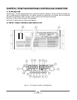
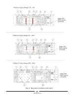
Page 31: ...83 530 000 Rev G 28 Fig 4 2 Rear panel connections and controls...


