


83-530-000 Rev. G
15
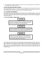
Some components inside the power supply are at AC/DC
voltage even when the On/Off switch is in the “Off” position.
To avoid electric shock hazard, disconnect the line and load
and wait 15 minutes before removing cover.
There is a potential shock hazard if the power supply chassis
(with cover in place) is not connected to an electrical safety
ground via the safety ground in the AC input stud terminals.
2. Use a support bar to provide adequate support for the rear of the power supply. Do not obstruct the
air exhaust at the rear panel of the unit.
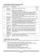
3.5 LOCATON, MOUNTING AND COOLING
This power supply is fan cooled. The air intake is at the front panel and the exhaust is at the rear panel.
Upon installation allow cooling air to reach the front panel ventilation inlets. Unrestricted air space at
the front and the rear of the unit is necessary for proper cooling of power supply.
3.6 AC SOURCE REQUIREMENTS
The Genesys
TM
series can be operated from a nominal 208V, 400V or 480V three phase, 4 wire, 47
63
Hz. The input voltage range and current required for each model is specified in Chapter 2. Ensure that
under heavy load, the AC voltage supplied to the power supply does not fall below the specifications
described in Chapter 2.
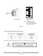
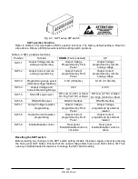
3.7 AC INPUT POWER CONNECTION
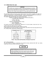
The customers AC line connects to the power supply through four stud type terminals. Only use a
power cable with the correct voltage and current ratings. The recommended wire gauge is listed in the
table in section 3.7.1. The ground wire must be equal to or larger than the recommended gauge for
phase. The power supply must be permanently connected to an approved AC distribution box with
suitably rated overcurrent protection (60Amp UL Listed fuse for 208V input, and 40 Amp UL listed fuse
for 400/480 input).
Connection of this power supply to an AC power source should
be made by an electrician or other qualified personnel. Do not
exceed the torque specified on input stud terminals.
CAUTION
WARNING
WARNING
Summary of Contents for GENESYS 10KW
Page 2: ......
Page 3: ......
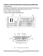
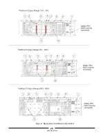
Page 31: ...83 530 000 Rev G 28 Fig 4 2 Rear panel connections and controls...


