


83-530-000 Rev G
36
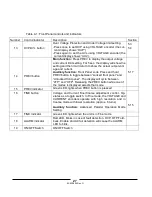
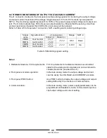
When the unit is shut-off by J1 signal, the VOLTAGE display will show “SO” to indicate the unit state. J1 contact
15 is the SO signal input and contacts 2 and 3, IF_COM, are the signal return (connected internally). Contacts 2, 3
and 15 are optically isolated from the power supply output.
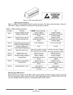
The SO control logic can be selected by the rear panel SW1 Setup switch. Refer to Table 5-2 for SW1 setting and
SO control logic.
SW1-5 setting
SO signal level
J1-2(3), 15
Power supply
output
Display
Down (default)
2-15V or Open
0-0.6V or Short
On
Off
Voltage/Current
“SO”
Up
2-15V or Open
0-0.6V or Short
Off
On
“SO”
Voltage/Current
Table 5-2: SO logic selection
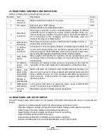
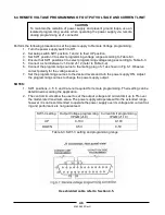
5.8 ENABLE/DISABLE CONTROL VIA REAR PANEL J1 CONNECTOR
Contacts 1 and 14 of J1 (Fig.4-2, item 5) serve as Output Enable/Disable terminals by switch or relay. This func-
tion is enabled or disabled by the SW1 Setup switch position 9. Refer to Table 5-3 for Enable/Disable function and
SW1 setting.
SW1-9 setting
Enable/Disable inputs
Power supply output
Display
ALARM LED
Down (Default)
Open or Short
On
Voltage/Current
Off
Open
Off
“ENA”
Blinking
Up
Short
On
Voltage/Current
Off
Table 5-3: Enable/Disable function and SW1 setting
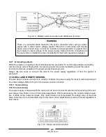
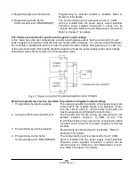
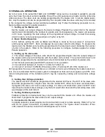
5.9 CV/CC SIGNAL
CV/CC signal indicates the operating mode of the power supply, Constant Voltage or Constant Cur-
rent.
CV/CC signal is an open collector output with a 30V parallel zener, at J1-13, referenced to the COM potential
at J1-12 (connected internally to the negative sense potential). When the power supply operates in Constant Volt-
age mode, CV/CC output is open. When the power supply operates in Constant Current mode, CV/CC signal out-
put is low (0-0.6), with maximum 10mA sink current.
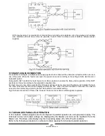
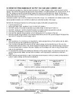
5.10 PS_OK SIGNAL
PS_OK signal indicates fault condition in the power supply. PS_OK is a TTL signal output at J1-16, referenced to
IF_COM at J1-2, 3 (Isolated Interface Common). When a fault condition occurs, PS_OK level is low, with maxi-
mum sink current of 1mA; when no fault condition occurs, PS_OK level is high with maximum source current of
2mA. The following faults will set the PS_OK to Fault state:
*OTP
*Enable/Disable open
*OVP
*SO (Rear panel Shut-Off)
*Foldback
*IEEE failure (With optional IEEE interface)
*AC fail
*Output Off
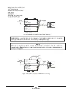
CAUTION
To prevent possible damage to the unit, do not connect any of the
Enable/Disable inputs to the positive or negative output potential.
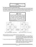
If the Enable/Disable inputs are opened when the unit is in Safe Start mode, it is re-
quired to short the Enable/Disable inputs and then press OUT button or send OUT1
command to resume operation.
CAUTION
Do not connect CV/CC signal to a voltage source higher than 30VDC,
Always connect CV/CC signal to the voltage source with a series resistor
to limit the sink current to less than 10mA.
Summary of Contents for GENESYS 10KW
Page 2: ......
Page 3: ......
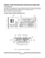
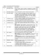
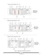
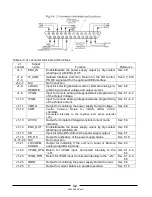
Page 31: ...83 530 000 Rev G 28 Fig 4 2 Rear panel connections and controls...


