


83-530-000 Rev. G
45
CAUTION
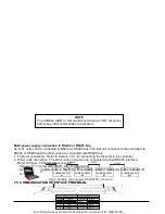
COM (J1-12), VPGM_RTN (J1-22) AND IPGM_RTN (J1-23) terminals of J1
connect internally to the -Sense potential (-LS). Do not connect these termi-
nals to any potential other than -Sense (-LS), as it may damage the power
supply.
CAUTION
When the Isolated Analog Option is installed, do not apply any signals to the
non-isolated VPGM and IPGM (J1-9 and J1-10) pins. All other J1 features
may be used normally. Refer to Section 4.5 for a description of J1 features.
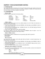
CHAPTER 6 REMOTE ANALOG PROGRAMMING
6.1 INTRODUCTION
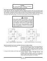
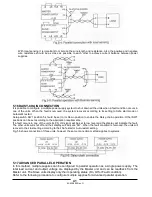
The rear panel connector J1 allows the user to program the power supply output voltage and current
limit with an analog device. J1 also provides monitoring signals for output voltage and output current.
The programming range and monitoring signals range can be selected between 0-5V or 0-10V using
the setup switch SW1. When the power supply is in Remote Analog programming, the serial communi-
cation port is active and can be used to read the power supply parameters.
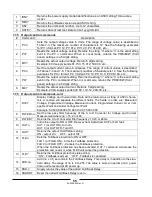
6.2 LOCAL/REMOTE ANALOG INDICATION
Contact 8 of J1 (Fig.4-2, Item 5) accepts TTL signal or Open-Short contact (referenced to J1-12) to
select between Local or Remote Analog programming of the output voltage and current limit.
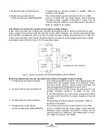
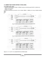
In Local mode, the output voltage and current limit can be programmed via the front panel VOLTAGE
and CURRENT encoders or via the RS232/485 port. In Remote Analog mode, the output voltage and
current limit can be programmed by analog voltage or by programming resistors via J1 contacts 9 and
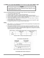
10 (refer to Sections 6.4 and 6.5). Refer to Table 6-1 for Local/Remote Analog control (J1-8) function
and Setup switch SW1-1, 2 setting.
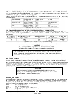
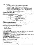
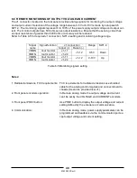
Table 6-1: Local/Remote Analog control function
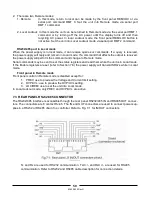
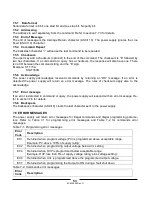
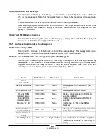
6.3 LOCAL/REMOTE ANALOG INDICATION
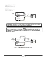
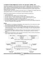
Contact 21 of J1 (Fig. 4-2, Item 5) is an open collector output that indicates if the power supply is in
Local mode or in Remote Analog mode. To use this output, connect a pull-up resistor to a voltage
source of 30Vdc maximum. Choose the pull-up resistor so that the sink current will be less than 5mA
when the output is in low state. Refer to table 6-2 for J1-21 function.
Table 6-2: Local/Remote Analog indication
SW1-1, 2 setting
J1-8 function
Output voltage/
Current setting
Down (default)
No effect
Local
“0” or Short
Remote
Up
“1” or Open
Local
J1-8
SW1-1
SW1-2
J1-21 signal
Analog Mode
Down
Down
Open
Local
Down
Up
0
0.6V
Remote
Up
Down
0
0.6V
Remote
TTL “0” or short
Up
Up
0
0.6V
Remote
TTL “1” or open
Down or Up
Down or Up
Open
Local
Summary of Contents for GENESYS 10KW
Page 2: ......
Page 3: ......
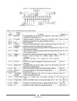
Page 31: ...83 530 000 Rev G 28 Fig 4 2 Rear panel connections and controls...


