


83-530-000 Rev. G
31
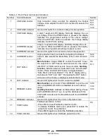
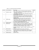
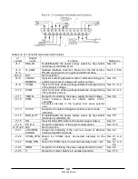
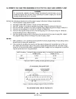
4.5 REAR PANEL J1 PROGRAMMING AND MONITORING CONNECTOR
The J1 Programming and Monitoring connector is a DB25 subminiature connector located on the
power supply rear panel. Refer to Table 4-4 for description of the connector functions. The power sup-
ply default configuration is Local operation, which does not require connections to J1. For remote op-
eration using J1 signals use the plug provided with power supply or equivalent type. It is essential to
use plastic body plug to conform to Safety Agency requirements. Shielded cable is required to maintain
EMC Specification for J1 wires. Connect the shield to a power supply chassis ground screw.
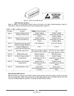
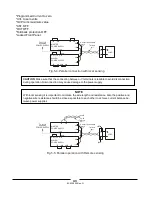
4.5.1
Making J1 connections
-J1 connector type: AMP, P/N: 747461-3
-J1 plug description: AMP, P/N: 745211-2
-Wire dimension range: AWG26-22
-Extraction tool: AMP, 91232-1 or equivalent.
-Manual Pistol grip tool:
Handle: AMP, P/N: 58074-1
Head: AMP, P/N: 58063-1
Before making any connection, turn the power switch to the Off position and wait until the front panel
display has turned Off.
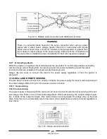
Terminals 12, 22 and 23 of J1 are connected internally to the
negative sense (-LS) potential of the power supply. Do not
attempt to bias any of these terminals relative to the negative
local sense. Use the Isolated Programming interface option to
allow control from a programming source at a different poten-
tial relative to the power supply negative.
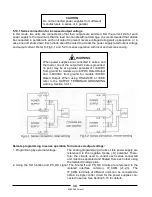
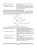
To prevent ground loops and to maintain the isolation of the
Power supply when programming from J1, use an
Ungrounded programming source.
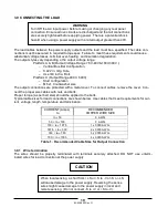
WARNING
There is a potential shock hazard at the output when using a
power supply with rated output greater than 40V. Use wires
with minimum insulation rating equivalent to the maximum
output voltage of the power supply.
CAUTION
CAUTION
Summary of Contents for GENESYS 10KW
Page 2: ......
Page 3: ......
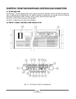
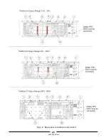
Page 31: ...83 530 000 Rev G 28 Fig 4 2 Rear panel connections and controls...


