


Fuel
Dispensers
TATSUNO
EUROPE
‐
Installation
and
User
Manual
,
revision
10,
January
2022
85
2.6.2.
LIQUEFIED
PROPANE
‐
BUTANE
(LPG)
DISPENSER/MODULE
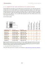
Figure
52
‐
Basic
parts
of
the
LPG
dispensing
module
and
its
cover
Position
Device
Position
Device
Position
Device
1
Dispensing
module
foundation
8
Electro
‐
magnetic
valve
15
Manometer
2
Input
ball
valve
(fluid)
9
Sight
hole
‐
‐
3
Piston
meter
LPG
10
Delivery
hoses
K1
Column
lid
LPG
rear
4
Overpressure
valve
11
Delivery
nozzles
K2
Column
lid
LPG
5
Pulser
–
pulse
generator
12
Nozzle
cover
K3
LPG
module
roof
6
Output
ball
valve
(gas)
13
Gaseous
phase
separator
K4
LPG
module
door
7
Differential
valve
14
Filter
K5
Front
column
LPG
2.6.3.
REDUCTION
AGENT
AUS
32
(ADBLUE®)
DISPENSER/MODULE
Figure
53
‐
Basic
parts
of
the
AdBlue®
dispensing
module
and
its
cover
Position
Device
Position
Device
Position
Device
1
Dispensing
module
foundation
7
Electro
‐
magnetic
valve
K3
Hydraulics
roof
2
Input
ball
valve
8
Filter
K4
Module
hydraulics
door
3
Heating
distribution
box
9
Nozzle
cover
K5
AdBlue®
hose
door
4
AdBlue®
piston
meter
‐
‐
K6
Column
lid
rear
combi
5
Pulser
–
pulse
generator
K1
Column
lid
K7
Front
column
combi
6
Heating
element
(ATEX)
K2
AdBlue®
cover,
front
‐
‐


