


58
TASCAM SS-CDR250N / SS-R250N
8 – Recording
Setting mic/line input sensitivity
Before starting recording, input gains should be adjusted to
prevent recorded sounds or signals from being distorted due to
excessive input levels and to prevent them from being so low
that they are below the noise floor.
NOTE
This item will not appear when the input source is set to any-
thing other than
ANALOG BALANCED
1.
Select
BAL.INPUT GAIN
on the
REC 1
page to open the
BALANCED INPUT GAIN
screen. (See “Menu operation pro-
2.
Set the mic input sensitivity.
Option
Meaning
LINE
(default)
Use when connecting the line output jacks
of external devices to this unit’s MIC/LINE
IN (BALANCED) L/R jacks.
MIC-LOW
Use when mics are connected to the MIC/
LINE IN (BALANCED) L/R jacks.
MIC-HIGH
NOTE
When
REC SET LINK
is set to
OFF
on the
REC 1
page, the lev-
els of the left and right channel inputs are adjusted separate-
ly. (See “Setting left/right channel inputs separately” on page
57.)
3.
Confirm the setting and return to the Menu Screen.
Adjusting input signal levels
Use the following procedures to adjust input signal levels.
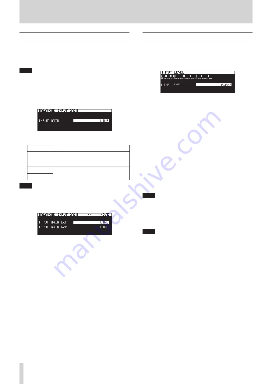
1.
Select
INPUT LEVEL
on the
REC 1
page to open the
INPUT
LEVEL
screen. (See “Menu operation procedures” on page
INPUT LEVEL
screen when adjusting line level
2.
Adjust the input signal levels.
LINE LEVEL
(when
BALANCE INPUT GAIN
screen set to
LINE
)
Options:
-inf
,
-54dB
,
-48dB
,
-42dB
,
-36dB
,
-30dB
,
-24dB
,
-20dB
,
-16dB
,
-12dB
,
-10dB
,
-8dB
,
-6dB
–
0.0dB
(default) –
+6.0dB
(
0.5dB
increments),
+7.0dB
–
+18.0dB
(
1.0dB
increments)
MIC LEVEL
(when
BALANCE INPUT GAIN
screen setting is
MIC-LOW
or MIC-HIGH)
Options:
MUTE
(minimum),
-4.0dB
–
0.0dB
(default) –
+6.0dB
(
0.5dB
increments),
+7.0dB
–
+31.0dB
(1.0
dB
incre-
ments),
+31.5dB
DIGITAL LEVEL
(
INPUT SELECT
screen set to
DIGITAL CO-
AXIAL
,
DIGITAL XLR
or
IF-DA2 (DANTE)
)
Options:
-6.0dB
–
0.0dB
(default value,
0.1dB
incre-
ments) –
+6.0dB
NOTE
When
REC SET LINK
is set to
OFF
on the
REC 1
page, the lev-
els of the left and right channel inputs are adjusted separate-
ly. (See “Setting left/right channel inputs separately” on page
57.)
3.
Confirm the setting and return to the Menu Screen.
NOTE
You can use the level meters shown on the
INPUT LEVEL
screen to check input levels as you adjust them.
Set the level
so that they are as high as possible without exceeding the
level meter peak levels.


