Physical Description
59
ID: um_tsmux
CP525 cMux User’s Manual Rev. 5.20.12 (3944)
6.1.8 Power Supply
Section
provides details of the power supply, protective earth and security. Read all these
instructions, prior to connecting the units power cable.
6.1.9 Ethernet Management Port
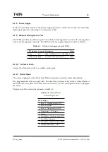
The CP525 provides one Ethernet port for control and management. Connect the management
port to the management network. The LEDs for the management port are used as follows:
Table 6.7
Ethernet management port LEDs
LED indicator Location Description
Colour
Speed
Left
Unlit = 10 Mbit/s, Lit = 100 Mbit/s Green
Traffic and link Right
Lit=Link, Blink=data tx or rx
Green
6.1.10 Technical Earth
Connect the Technical earth to a suitable earth point.
6.1.11 Alarm/Reset
The unit is equipped with a 9-pin male DSub connector to provide alarm information.
Two programmable relays are provided. The first relay is always activated on a critical alarm or
when the unit is not powered. Please refer to section
for a description of how to program
the relays.
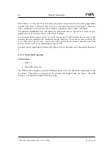
The pin out of the connector is shown in table
Table 6.8
Alarm/Reset
connector pin out
Pin Function
1. Relay 2 - Closed on alarm (NC)
2. Relay 2 Common
3. Relay 2 - Open on alarm (NO)
4. Prepared for +5V Output
5. Ground
6. Alarm Relay - Closed on alarm (NC)
7. Alarm Relay Common
8. Alarm Relay - Open on alarm (NO)
9. Optional Reset Input / GPI
Summary of Contents for CP525 cMux
Page 2: ......
Page 10: ......
Page 12: ...12 CP525 cMux User s Manual Rev 5 20 12 3944 ID um_tsmux ...
Page 18: ...18 CP525 cMux User s Manual Rev 5 20 12 3944 ID um_tsmux ...
Page 24: ...24 CP525 cMux User s Manual Rev 5 20 12 3944 ID um_tsmux ...
Page 66: ...66 CP525 cMux User s Manual Rev 5 20 12 3944 ID um_tsmux ...
Page 238: ...238 CP525 cMux User s Manual Rev 5 20 12 3944 ID um_tsmux ...
Page 248: ...248 CP525 cMux User s Manual Rev 5 20 12 3944 ID um_tsmux ...
Page 276: ...276 CP525 cMux User s Manual Rev 5 20 12 3944 ID um_tsmux ...

