Chapter 2
Hardware Installation
15
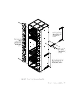
FIGURE 2-3
Support Rail and Fixings (19-inch Rack)
The mounting screws should be placed in position pairs E1 and F1, E2 and F2, E3
and F3, E4 and F4 or E5 and F5. The pair of holes to be used depends on the front-
to-back depth of the rack (mounting flange to mounting flange). The holes marked
with the appropriate figure, as shown in
TABLE 2-2
, should be closest to the rear of
the chassis.
The slots labeled G are used for mounting the rear flanges (see
FIGURE 2-6
on
page 17). Only one of the vertical pairs of holes in the rear flanges should be used.
The spacers must be placed with the flat side towards the chassis and the
countersink towards the support rail (see
FIGURE 2-4
).
TABLE 2-2
Support Rail Screw Hole Locations
Rack depth
Screw holes
480 mm
E5 and F5
530 mm
E4 and F4
580 mm
E3 and F3
630 mm
E2 and F2
680 mm
E1 and F1
E5
E4
E3
E2
E1
F5
F4
F3
F2
F1
G
G
Spacer (340-5483)
Spacer
Summary of Contents for Netra ft 1800
Page 6: ...vi Netra ft 1800 Installation Guide February 1999 ...
Page 10: ...x Netra ft 1800 Installation Guide February 1999 ...
Page 40: ...26 Netra ft 1800 Installation Guide February 1999 FIGURE 2 12 Removing a CPUset Module ...
Page 41: ...Chapter 2 Hardware Installation 27 CAF Modules FIGURE 2 13 Removing a CAF ...
Page 43: ...Chapter 2 Hardware Installation 29 PSU Modules FIGURE 2 15 Removing a Power Supply ...
Page 45: ...Chapter 2 Hardware Installation 31 FIGURE 2 16 Removing an RMM Module ...
Page 56: ...42 Netra ft 1800 Installation Guide February 1999 ...


