24
Netra ft 1800 Installation Guide • February 1999
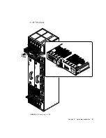
FIGURE 2-11
Module Injector/ejector Lever
The module is disengaged from its electrical connection when the slide is moved
towards the rounded end of the lever, exposing the red warning dot.
The general procedure refers to CPUset, CAF, PCI and PSU modules. For more
specific instructions for the RMM and disk chassis, refer to:
■
“Replacing an RMM” on page 30
■
“Replacing a Disk Chassis” on page 32
▼
To Remove a Module
1. Move the slide in the lever on the module to the disengaged position.
This will expose the red warning dot.
2. Lower the lever.
The module will slide out a small amount when the lever is fully lowered.
3. Slide the module out of its slot, using the handle if there is one.
For specific procedures relating to individual modules, refer to:
■
“CPUset Modules” on page 25
■
“CAF Modules” on page 27
■
“PCI Modules” on page 28
■
“PSU Modules” on page 29
Open
Closed
Red warning dot
Summary of Contents for Netra ft 1800
Page 6: ...vi Netra ft 1800 Installation Guide February 1999 ...
Page 10: ...x Netra ft 1800 Installation Guide February 1999 ...
Page 40: ...26 Netra ft 1800 Installation Guide February 1999 FIGURE 2 12 Removing a CPUset Module ...
Page 41: ...Chapter 2 Hardware Installation 27 CAF Modules FIGURE 2 13 Removing a CAF ...
Page 43: ...Chapter 2 Hardware Installation 29 PSU Modules FIGURE 2 15 Removing a Power Supply ...
Page 45: ...Chapter 2 Hardware Installation 31 FIGURE 2 16 Removing an RMM Module ...
Page 56: ...42 Netra ft 1800 Installation Guide February 1999 ...


