Chapter 2
Hardware Installation
37
FIGURE 2-21
Small Filter Tray
1. Insert the trays into the appropriate apertures at the base of the chassis; the two
large trays are fitted on the left and the small tray on the right.
It is unimportant which way up the trays are fitted.
2. Push the trays securely home and hand-tighten the two thumbscrews on each.
The thumbscrews are inserted into the tapped threads exposed by removal of the
sacrificial mounting plinth.
Summary of Contents for Netra ft 1800
Page 6: ...vi Netra ft 1800 Installation Guide February 1999 ...
Page 10: ...x Netra ft 1800 Installation Guide February 1999 ...
Page 40: ...26 Netra ft 1800 Installation Guide February 1999 FIGURE 2 12 Removing a CPUset Module ...
Page 41: ...Chapter 2 Hardware Installation 27 CAF Modules FIGURE 2 13 Removing a CAF ...
Page 43: ...Chapter 2 Hardware Installation 29 PSU Modules FIGURE 2 15 Removing a Power Supply ...
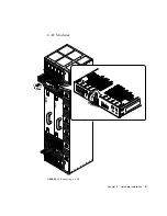
Page 45: ...Chapter 2 Hardware Installation 31 FIGURE 2 16 Removing an RMM Module ...
Page 56: ...42 Netra ft 1800 Installation Guide February 1999 ...


