12
Netra ft 1800 Installation Guide • February 1999
1. Remove all modules except the motherboards from the chassis and put them in a
safe place.
Refer to “Removing and Installing Modules” on page 23.
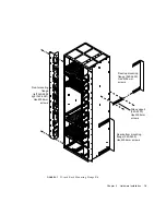
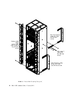
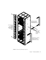
2. Using the Phillips No.2 screwdriver (supplied), remove the two Phillips screws
securing the four red brackets (two on each side) to the chassis (see
FIGURE 2-1
).
You may also need to remove the brackets from the pallet. Use the Allen key
supplied to remove the two Allen screws from each bracket. The brackets are not
attached to the red mounting plinth.
3. Install the appropriate mounting flanges.
Refer to “Mounting Flanges” on page 13.
4. Use an appropriate lifting device to lift the chassis by the red mounting plinth,
and install it in the rack.
Caution –
If using a fork-lift device, ensure the tines of the lift extend right through
the mounting plinth and beyond the rear of the chassis. The chassis could deform if
you use incorrect lifting techniques.
5. Secure the chassis into the rack using the appropriate mounting points.
See “Mounting Flanges” on page 13.
6. Remove the mounting plinth.
Use the No.2 Phillips screwdriver supplied to remove the four screws from the front
and the three screws from the rear.
Mounting the chassis with the plinth attached ensures that the minimum amount of
clearance for air flow is provided beneath the system.
7. Install the two large and one small filter trays in the spaces immediately beneath
the chassis revealed by the removal of the plinth.
Refer to “To Install the Filter Trays” on page 36. The filter tray thumbscrews are
inserted in the tapped threads exposed by removal of the mounting plinth.
8. Install the modules into their appropriate locations.
Refer to “Removing and Installing Modules” on page 23.
Summary of Contents for Netra ft 1800
Page 6: ...vi Netra ft 1800 Installation Guide February 1999 ...
Page 10: ...x Netra ft 1800 Installation Guide February 1999 ...
Page 40: ...26 Netra ft 1800 Installation Guide February 1999 FIGURE 2 12 Removing a CPUset Module ...
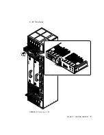
Page 41: ...Chapter 2 Hardware Installation 27 CAF Modules FIGURE 2 13 Removing a CAF ...
Page 43: ...Chapter 2 Hardware Installation 29 PSU Modules FIGURE 2 15 Removing a Power Supply ...
Page 45: ...Chapter 2 Hardware Installation 31 FIGURE 2 16 Removing an RMM Module ...
Page 56: ...42 Netra ft 1800 Installation Guide February 1999 ...


