6
Netra ft 1800 Installation Guide • February 1999
Mechanical Considerations when Mounting in the
Equipment Frame
Caution –
Mechanical assistance is required if installing a loaded chassis.
If you intend not to use a lifting device for installation, all modules other than the
motherboards must be removed from the system prior to lifting. The empty chassis
weighs approximately 49 kg (108 lb), or 68 kg (150 lb) with the motherboards, plus
the adaptors. The weight of any removable module depends on its configuration.
Weight warning labels are for guidance only.
See “Removing and Installing Modules” on page 23 for information about adding
modules to the motherboard.
The Netra ft 1800 chassis has been designed to accommodate most mounting
configurations. Adaptor flanges to suit 19-inch, 23-inch, 24-inch and 600-mm (ETSI)
rack sizes are available as required.
The Netra ft 1800 system is shipped with a plinth, which protects the bottom of the
chassis during transit and handling, and also ensures that the correct airflow inlet
plenum is provided during installation. The plinth must be removed once the
Netra ft 1800 is installed in a rack, then stored in a safe place.
The Netra ft 1800 chassis must be mounted using screws suitable for the equipment
frame. The screws should be M5, M6 or 10-32 UNF. All screws must be fitted. The
recommended tightening torque value for either M5 or 10-32 UNF recess head
screws is 3.8 Nm (2.8 lbf/ft), and that for M6 screws is 6 Nm (4.4 lbf/ft).
Mounting Requirements
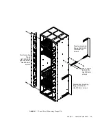
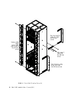
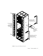
The Netra ft 1800 is available with the following removable mounting flanges:
■
19 inch EIA pattern
■
23 inch EIA pattern
■
24 inch EIA pattern
■
600 mm IEC917 (ETSI) pattern
Any of these flanges can be fitted in the following positions:
■
Flush with the front of the system
■
65 mm (2.56 inches) from front of system
■
196.1 mm (7.72 inches) from front of system
The second and third positions are intended for use with 5-inch web open frames
(relay racks).
Summary of Contents for Netra ft 1800
Page 6: ...vi Netra ft 1800 Installation Guide February 1999 ...
Page 10: ...x Netra ft 1800 Installation Guide February 1999 ...
Page 40: ...26 Netra ft 1800 Installation Guide February 1999 FIGURE 2 12 Removing a CPUset Module ...
Page 41: ...Chapter 2 Hardware Installation 27 CAF Modules FIGURE 2 13 Removing a CAF ...
Page 43: ...Chapter 2 Hardware Installation 29 PSU Modules FIGURE 2 15 Removing a Power Supply ...
Page 45: ...Chapter 2 Hardware Installation 31 FIGURE 2 16 Removing an RMM Module ...
Page 56: ...42 Netra ft 1800 Installation Guide February 1999 ...


