18
Netra ft 1800 Installation Guide • February 1999
23-inch, 24-inch and 600mm Mountings
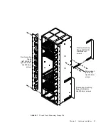
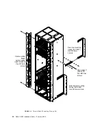
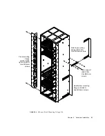
The 23-inch, 24-inch and 600mm mounting kits consist of the following items:
Refer to
FIGURE 2-7
on page 19 for 23-inch kits,
FIGURE 2-8
on page 20 for 24-inch kits
and
FIGURE 2-9
on page 21 for 600mm kits.
The sides of the system chassis are provided with tapped screwholes as shown in
FIGURE 2-2
on page 14.
Fit the front brackets using the screwholes in columns C and D, or just column C, or
just column D.
Screw the slide mounts to holes A and B in rows 1, 4, 7 and 10. You can then screw
the rear brackets to the rear of the rack (see
FIGURE 2-7
,
FIGURE 2-8
and
FIGURE 2-9
)
and slide the chassis onto the brackets until the front brackets are flush with the
front of the rack.
TABLE 2-3
23-inch, 24-inch and 600mm Mounting Flange Kits
Part number
Quantity
Item
23-inch
24-inch
600mm
1
Front left-hand mounting flange
340-4592
340-5445
340-5328
1
Front right-hand mounting flange
340-4591
340-5446
340-5329
2
Rear top mounting flange
340-5449
340-5447
340-5331
2
Rear bottom mounting flange
340-5450
340-5448
340-5427
8
Support rails
340-5330
340-5330
340-5330
6
Cable hook bracket with hooks already
installed
340-5553
340-5553
340-5553
40
M5 6mm panhead screws (for front and rear
flanges)
N/A
N/A
N/A
16
M5 8mm countersunk screws (for support
rails)
N/A
N/A
N/A
Summary of Contents for Netra ft 1800
Page 6: ...vi Netra ft 1800 Installation Guide February 1999 ...
Page 10: ...x Netra ft 1800 Installation Guide February 1999 ...
Page 40: ...26 Netra ft 1800 Installation Guide February 1999 FIGURE 2 12 Removing a CPUset Module ...
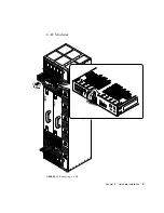
Page 41: ...Chapter 2 Hardware Installation 27 CAF Modules FIGURE 2 13 Removing a CAF ...
Page 43: ...Chapter 2 Hardware Installation 29 PSU Modules FIGURE 2 15 Removing a Power Supply ...
Page 45: ...Chapter 2 Hardware Installation 31 FIGURE 2 16 Removing an RMM Module ...
Page 56: ...42 Netra ft 1800 Installation Guide February 1999 ...


