(© Oct, 2007)
Compact CW Series Installation, Operation & Maintenance Manual
Air Technology Systems, Inc.
1-5
1.5.6
Temperature/Humidity Sensor
As a standard for room air control, a temperature/
humidity (T/H) sensor is factory mounted in the return
air stream. The (T/H) sensor monitors the return air
conditions and provides input signal(s) to the system
controller to manage the operation of the A/C unit
consistent with the setpoints entered in the system
controller.
1.5.7
Humidifier (Optional)
Compact CW systems utilize an electrode, steam
humidifier. The humidifier is factory installed inside the
air conditioner and includes fill and drain valves and
associated piping. Operation of the humidifier’s fill and
drain cycles is based on water conductivity and is
maintained by the humidifier controller. An operating
manual for the humidifier is provided under separate
cover. Refer to that manual for detailed information on
operation of the humidifier.
1.6 Optional Equipment
1.6.1
Condensate Pump
An optional condensate pump may be used for auto-
matic removal of condensate from the air conditioner
and flush water from the humidifier. An internal overflow
safety switch is wired to the system controller to
automatically shut down the precision A/C system
should an overflow occur.
1.6.2
Smoke Detector
Optionally mounted in the return air stream, a photo-
electric smoke detector is used to sense the presence
of smoke and signal the controller when a smoke
alarm condition exists.
1.6.3
Firestat
Optionally mounted in the return air stream, a fire
detector senses high retun air temperature and signals
the controller when a fire alarm condition exists.
1.6.4
Auto Transfer Switching
An automatic transfer, main power switching system is
optionally available for critical operation. With this
option, two main power service disconnect switches are
provided on the door of the cabinet to connect two
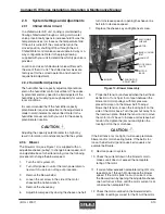
independent power sources, (see Figure 2). If the user
selectable, main power source is interrupted, or if a
phase loss or imbalance occurs, the automatic transfer
switching circuitry immediately transfers operation of
the precision A/C system to the secondary power
source. If power is transferred, the system controller
provides an alarm signal and the alarm display indicates
which power source failed. When the primary power
source is functionally restored, the A/C system load is
automatically transferred back to the primary power
source.
With the auto-transfer switching option, a preferred
power selection switch is mounted inside the cabinet
to the top of the electric box, (see Figures 1 & 3). This
switch may be used to manually transfer the power
source and/or to test the auto transfer switching
function.
1.6.4.1
Indicator Lights
As an additional option, an indicator light may be
provided above each main power service disconnect
switch for a visual indication that power is available.
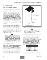
Figure 3- Preferred Power Selection Switch
Figure 2- Auto Transfer Disconnect Switches
OPTIONAL DUAL
DISCONNECT SWITCHES
(LOCATION MAY VARY)
INDICATOR LIGHTS
(OPTIONAL)
FRONT DOOR OF
A/C SYSTEM


