(© Oct, 2007)
Air Technology Systems, Inc.
Compact CW Series Installation, Operation & Maintenance Manual
STRUCTURE
R-VALUE
Ceiling
R-38
Wall
R-21
Floor
R-19
Door
R-5
2-1
2.0
INSTALLATION
2.1
Receiving the Equipment
Your
Compact CW precision A/C system has been
tested and inspected prior to shipment. To ensure that
your equipment has been received in excellent condi-
tion, make a visual inspection of the equipment
immediately upon delivery. Carefully remove the
shipping container and all protective packaging. Open
the access doors and thoroughly inspect the unit
interior for any signs of transit-incurred damage. If
there is shipping damage, it must be noted on the
freight carrier's delivery forms
BEFORE
signing for the
equipment. Any freight claims
MUST
be done through
the freight carrier. SATS ships all equipment FOB.
SATS can assist in the claim filing process with the
freight carrier. Should any damage be present, notify
the SATS Product Support Group prior to attempting
any repairs. Refer to section five of this manual for
instructions.
A Data Package has been sent with your unit. It
contains this manual, a supplemental microprocessor
controller manual, system drawings, applicable
MSDS’s, other component manuals, warranty registra-
tion and other applicable instructions based on the
configuration and options of your unit. The data
package has been placed in your unit in a clear plastic
bag. These documents need to be retained with the
unit for future reference.
NOTE
Items that have been shipped loose, such as
controllers, temperature/humidity sensors, wa-
ter detectors, etc., are shipped inside the air
conditioner, unless specified otherwise by the
customer. The filter box or plenum box assem-
bly (if applicable) is shipped separately. Unpack
and store these items in a safe place unless
you are using them immediately.
2.2
Site Preparation
Compact CW systems are designed with easy service
access in mind. Component access panels are
located on the front of the equipment. The number of
panels may vary depending on size and configuration
of the unit. Each unit has one front hinged panel for
accessing the electrical box. In order to have full
service access, no permanent obstructions can be
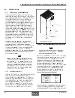
placed in front of the unit. See Figure 4 for the mini-
mum recommended clearance in front of the unit.
NOTE
Working clearance requirements need to be es-
tablished prior to mounting the unit. Refer to lo-
cal and national electrical codes.
To minimize the effects of the environment surrounding
the conditioned space, certain steps must be taken.
This is especially true for critical/precision room
preparation (computer rooms/labs) requiring close
tolerance control of temperature and humidity. The
conditioned space should be well insulated and
include a vapor barrier. The installer should ensure that
the proper insulation rating is used based on the
design of the space, which was the basis for the
system selected. The following chart is a recom-
mended minimum R-value (thermal resistance) to
ensure optimum equipment operation.
The vapor barrier is the single most important require-
ment for maintaining environmental control in the
conditioned space. The vapor barrier in the ceiling and
40.0"
(MINIMUM FRONT
CLEARANCE)
SEE NOTE
NOTE: FOR UPFLOW UNITS, ALLOW SPACE ON
SIDES TO PERMIT ENTRANCE OF PIPING AND WIRING.
SEE NOTE
SERVICE
DISCONNECT SWITCH
Figure 4- Recommended Installation Clearance


