(© Oct, 2007)
Air Technology Systems, Inc.
Compact CW Series Installation, Operation & Maintenance Manual
TABLE OF CONTENTS
(Continued)
ii
List of Figures
Figure 1
Typical Internal Layout ............................ 1-4
Figure 2
Auto Transfer Disconnect Switches ........ 1-5
Figure 3
Preferred Power Selecton Switch ............ 1-5
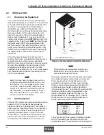
Figure 4
Installation Clearance ............................. 2-1
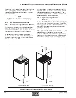
Figure 5
Typical Installation Upflow ....................... 2-2
Figure 6
Typical Installation Downflow ................... 2-2
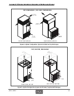
Figure 7
Downflow Configuration
Typical Air Patterns ................................ 2-3
Figure 8
Upflow Configuration Typical
Air Patterns (Top Discharge) ................... 2-4
Figure 9
Upflow Configuration Typical Air
Patterns (Top Ducted Discharge) ............ 2-4
Figure 10 Optional Floor Stand Installation ............. 2-5
Figure 11
Condensate Pump .................................. 2-7
Figure 12 Sample Nameplate ................................. 2-8
Figure 13 Electric Box ........................................... 2-9
Figure 14 Blower Assembly .................................. 2-10
Appendix A - Forms
Checklist for Completed Installation ......................... A-1
Periodic General Maintenance
Checks and Service Checklist .................................. A-2
Appendix B - Glossary
Definition of Terms and Acronyms ............................ B-1


