background image

(© Oct, 2007)

Compact CW Series Installation, Operation & Maintenance Manual

Air Technology Systems, Inc.

2-6

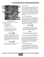
CAUTION


Take care not to damage the exposed tempera-
ture/humidity sensors on the PC board while screw-
ing in the cover fastening screw. The sensors can
be damaged if handled improperly.

2.6.5.1 Types of control

Room Air Control (standard)- The A/C unit is provided
with a temperature and humidity (T/H) sensor, factory
mounted in the return air stream of the A/C unit. The
return air temperature and humidity are monitored by
the system controller and compared to limit values set
at the factory. Control outputs are based on setpoints
entered into the system controller by the user.

As an alternative to locating the T/H sensor inside the
A/C unit, it may be field installed on a wall in the
conditioned space for sensing actual room conditions.

Supply Air Control- As an option, a field installed T/H
sensor may be used for supply air control. The sensor
is field installed in the supply air stream. The supply
air temperature and humidity are monitored by the
system controller and compared to limit values set at
the factory. Control outputs are based on setpoints
entered into the system controller by the user.

Room Air Control with Supply Air Limitation- The
controller monitors the T/H sensor located in the
return air stream and the T/H sensor located in the
supply air stream. Control is similar to “Room Air
Control” except, the temperature setpoint is automati-
cally increased by the controller when the measured
supply air temperature exceeds the Start Temperature
entered by the user. The extent of the setpoint
increase is determined by a factor which the user
enters in the controller as a gradient. A high gradient
significantly corrects the failure to meet the supply air
tempertaure but has the risk that the control circuit
starts to hunt.

With humidity control, the setpoint shift acts in the
opposite direction. If the starting humidity entered by
the user is exceeded by the measured supply air
humidity, the setpoint is autimatically reduced by the
controller. The user may also enter a gradient factor
for humidity control.

Formula:
New setpoint = old s [gradient • (start value -actual
value)]

Example (temperature): 70.5 = 70 + [0.5 • (61 - 60)]

Example (humidity):      49 = 50 + [0.5 • (70 - 72)]

Supply Air Control with Room Air Limitation- Based
on the same principle as “Room Air Control with
Supply Air Limitation” however, in this case the
setpoint shift works in the opposite direction on the
basis that the supply air is colder than the return air.
The temperature setpoint is automatically reduced by
the system controller when the measured room air
temperature exceeds the Start Temperature entered
by the user. The humidity setpoint is automatically
increased by the system controller when the mea-
sured room humidity drops below the starting humidity
entered by the user.

2.6.6

Remote Water Detector

The remote water detector is normally placed on the
sub-floor or in a field supplied auxiliary drain pan located
beneath the unit. SATS provides 2 types of water
detectors:

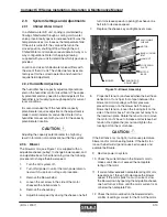
Spot type water detector-

Remove the protective cover and connect two control
wires to the terminals on the base
(terminal lugs are provided). Place the
water detector(s) on the floor with the
metal electrodes facing down. The base
is provided with a mounting hole in the
center which may be used to secure the water detec-
tor in place. Replace the cover. When water is present,
current will flow between the electrodes.

NOTE

Do not place the spot type water detector on
an electrically conductive surface.

Cable type water detector-

Lay the cable water detector flat across the sub-floor
where water could collect.
When water is present,
current will flow between the
two wires. A two conductor
wire harness is provided with a
quick connect fitting on the end. The harness mates to
the fitting on the water detector and connects it to the
control board inside the electric box.

2.7

Piping Connections

2.7.1

Chilled Water/Hot Water

For CCD (downflow) units, the pipe openings for the
chilled water and optional hot water reheat piping are
located in the base of the unit. For CCU (upflow) units,
pilot holes are provided inside the unit in the lower side
panel(s). These pilot holes may be enlarged from
inside the unit. Refer to the installation drawing

Summary of Contents for Compact CW Series

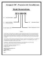
Page 1: ...Oct 2007 Compact CW Series Installation Operation Maintenance Manual Air Technology Systems Inc...

Page 2: ...uage for use by anyone other than the owner of the equipment for which this manual is written without the prior written consent of Stulz Air Technology Systems Inc SATS This document contains confiden...

Page 3: ...umidity Sensor 2 5 2 6 6 Remote Water Detector 2 6 2 7 Piping Connections 2 6 2 7 1 Chilled Water Hot Water 2 6 2 7 2 Condensate Drain 2 7 2 7 2 1 Gravity Drain 2 7 TABLE OF CONTENTS 2 7 2 2 Condensat...

Page 4: ...Installation Downflow 2 2 Figure 7 Downflow Configuration TypicalAir Patterns 2 3 Figure 8 Upflow Configuration Typical Air Patterns Top Discharge 2 4 Figure 9 Upflow Configuration TypicalAir Patterns...

Page 5: ...il at a rate that varies proportionally to the amount of cooling required to meet the user selectable tempera ture setpoint Heat from the surrounding air is trans ferred through the finned tubing of t...

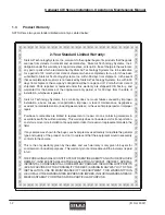
Page 6: ...nc s warranty does not cover failures caused by improper installation abuse misuse misapplication improper or lack of maintenance negligence accident normaldeterioration includingwearandtear ortheuseo...

Page 7: ...le of supporting the unit When working on electrical equipment remove all jewelry watches rings etc Always disconnect the main power supply to the equipment at the main power disconnect switch before...

Page 8: ...pply air as required to offset the sensible cooling of the system during the dehumidification cycle and for the automatic heating mode As a standard electric resis tance heating elements are factory i...

Page 9: ...ller when a smoke alarm condition exists 1 6 3 Firestat Optionally mounted in the return air stream a fire detector senses high retun air temperature and signals the controller when a fire alarm condi...

Page 10: ...d inside the air conditioner unless specified otherwise by the customer The filter box or plenum box assem bly if applicable is shipped separately Unpack and store these items in a safe place unless y...

Page 11: ...ocated inside or outside the conditioned space but are designed to supply air to only one room The Compact CW systems are front accessible which allows the units to be placed in a corner or between ca...

Page 12: ...as possible The return inlet is provided with a turned in flange on top of the unit for connection of the ductwork Refer to the installation drawing provided with the unit The connection of ductwork...
Page 13: ...TLET RETURN AIR INLET Figure 8 Upflow Configuration Typical Air Patterns Top Discharge SUPPLY AIR OUTLET RETURN AIR INLET FRONT FREE RETURN REAR DUCTED RETURN Figure 9 Upflow Configuration Typical Air...

Page 14: ...nsate pump may be provided for automatically eliminating condensate and humidifier flush water from the drain pan The conden sate pump is typically installed by the factory inside the A C unit If an o...

Page 15: ...educed by the controller The user may also enter a gradient factor for humidity control Formula Newsetpoint oldsetpoint gradient startvalue actual value Example temperature 70 5 70 0 5 61 60 Example h...

Page 16: ...freezing temperatures The diameter of the drain line should be the full size of the connection NOTE Pour some water into the condensate drain pan s prior to start up This fills the trap and prevents...

Page 17: ...tions are required WARNING Verify power is turned off before making connec tions to the equipment NOTE All wiring must conform to local and national elec trical code requirements Use of copper conduc...

Page 18: ...local and national electrical code requirements 2 7 3 1 Remote Temperature Humidity Sensor The remote temperature humidity sensor requires a three conductor shielded cable with the shield terminated a...

Page 19: ...motor see Figure 14 is supplied with an adjustable sheave pulley to change blower speed and an adjustable base for belt tensioning Use the following procedure to change the blower speed 1 Turn the A...

Page 20: ...cylinder is warm to verify if the humidifier is operational In all cases 1 to 6 hours might be required to see a desired level or rise in humidity in the conditioned space Once room conditions have b...

Page 21: ...ing components as automatic con trols may start them unexpectedly 4 1 1 Compact CW Precision A C Unit 4 1 1 1 Filter The filter is usually the most neglected item in an air conditioning system To main...

Page 22: ...A change cylinder light on the humidifier cabinet will illuminate red when the cylinder requires replacement NOTE The red light may illuminate during initial start up but it doesn t necessarily mean...

Page 23: ...Low hot water flow Check hot water flow at supply source Inoperable Inspect piping for leaks or obstructions b Low hot water supply temperature Check hot water supply c Temperature setpoint too low In...

Page 24: ...ing the Auto On Off Drain switch to the Drain position 4 4 3 When drained push the Auto On Off Drain switch to the Off position 4 Turn off power at the main power disconnect switch 5 The power wires t...

Page 25: ...ges If you do not have established credit with SATS you must provide a freight carrier account number A written or faxed purchase order is required on warranty parts and must be received prior to 12 0...

Page 26: ...Oct 2007 Air Technology Systems Inc Compact CW Series Installation Operation Maintenance Manual NOTES...

Page 27: ...ith water 8 Water supply line connected to humidifier if required 9 Safety pan installed under ceiling mounted equipment if required 10 Filter box installed if required 11 Filter s installed if requir...

Page 28: ...Oct 2007 Air Technology Systems Inc Compact CW Series Installation Operation Maintenance Manual...

Page 29: ..._ _ _ _ _ _ _ _ _ _ _ _ _ _ _ _ _ _ _ _ _ _ _ _ _ _ _ _ _ _ _ _ _ _ _ _ _ _ _ _ _ _ _ _ _ _ _ _ _ _ _ _ _ _ _ _ _ _ _ _ _ _ _ _ _ _ _ _ _ _ _ _ _ _ _ _ _ _ _ _ _ _ _ _ _ _ _ _ _ _ _ _ _ _ _ _ _ _ _ _...

Page 30: ...Oct 2007 Air Technology Systems Inc Compact CW Series Installation Operation Maintenance Manual...

Page 31: ...OB Freight on Board HACR Heating Air Conditioning Refrigeration HP Horse Power Hz Hertz IAQ IndoorAir Quality in w g Inches of Water Gauge KVA Kilo Volt Amps kW Kilowatt MAX CKT BKR Maximum Circuit Br...

Page 32: ...Oct 2007 Air Technology Systems Inc Compact CW Series Installation Operation Maintenance Manual...

Reviews: