(© Oct, 2007)
Compact CW Series Installation, Operation & Maintenance Manual
Air Technology Systems, Inc.
2-10
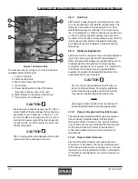
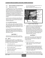
Figure 14- Blower Assembly
MOTOR
BASE
MOTOR
TENSION ROD
ADJUSTMENT
BLOWER
LOCK DOWN
PLATE
ADJUSTABLE
SHEAVE
JAM NUT
BASE LOCKING
BOLT
2.9
System Settings and Adjustments
2.9.1
Chilled Water Circuit
In a chilled water A/C unit, cooling is maintained by
flowing chilled water through a cooling coil. A water
valve proportionally opens to increase fluid flow as the
temperature rises (or closes as the temperature falls).
If the unit is turned off, the valve will return to the
closed position, shutting off flow through the coil.
Chilled Water control valves are available in 2-way or 3-
way configurations. Refer to the piping drawing
supplied with your unit to determine which type valve is
provided.
Location and size of chilled water valves differs with
the size of the A/C unit. The chilled water valves are
factory set for the correct operation and should not
require field adjustment.
2.9.2 Humidifier Adjustment
The humidifier has a capacity adjustment potentiom-
eter on the humidifier control circuit board. The capac-
ity potentiometer may need to be field adjusted if the
humidifier is not supplying enough capacity for current
room conditions.
It is recommended that if the humidifier capacity
potentiometer requires adjustment, the adjustment is
made in small increments and verified. Refer to the
humidifier manual sent with your unit for the capacity
potentiometer location.
CAUTION
Adjusting the capacity potentiometer too high may
result in formation of condensation within the system.
2.9.3
Blower
The blower motor (see Figure 14) is supplied with an
adjustable sheave (pulley), to change blower speed, and
an adjustable base for belt tensioning. Use the following
procedure to change the blower speed.
1.
Turn the A/C system off.
2.
Turn off all power to unit at the main power discon-
nect switch; use lock-out tag-out procedure.
3.
Remove the blower belt(s).
4.
Loosen the set screw in the side of the motor
sheave with an allen wrench.
5.
Remove the sheave key.
6.
Adjust blower speed by closing the sheave one half
turn to increase speed or opening the sheave one
half turn to decrease speed.
7.
Replace the sheave key and tighten set screw.
8.
Proper belt tension is achieved when the belt has a
deflection of ¾ inch per foot of span between the
blower and motor pulleys, with firm pressure
placed mid-span on the blower belt. To adjust
blower belt tension, loosen the locking bolt on the
side of the motor base. Turn the jam nut away from
the lockdown plate. Rotate the tension rod to move
the motor on it’s base to increase or decrease belt
tension. Re-tighten the jam nut and tighten the
locking bolt on the motor base.
CAUTION
If the belt tension is too tight, it will cause premature
blower and/or motor bearing failure. If the belt is too
loose, the belt will slip and cause belt squeals and
eventual belt failure.
9.
Restore power to system.
10. Check the current draw on the blower motor to
make sure it does not exceed the nameplate
rating of the motor.
11. If current draw exceeds nameplate rating of motor,
repeat steps 1 through 9 to decrease the blower
speed. If the motor pulls too much current, slow
the blower down by opening the adjustable sheave
one half turn at a time, until the motor current is at
or below the nameplate FLA.
12. Check the motor overload on the blower starter to
confirm its setting is correct for the FLA of the motor.

