


6-5
Routine Maintenance
Operator Manual
122993-622
•
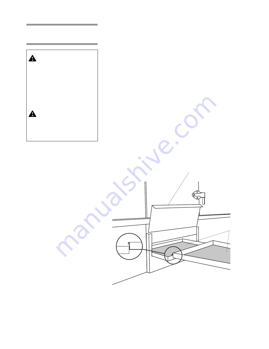
Chamber Solution Screen
NOTE: Clean chamber solution screens while they are still wet, before foreign
matter dries.
1.
Lock disconnect switch in
OFF
position and close building supply valves.
2.
Remove access panel from side of cabinet section.
3.
Slide screens out of chamber and separate screen pieces as they appear
(see Figure 6-1).
4.
Remove any debris from screens.
5.
Slide screens back into chamber. Ensure screen pieces are hooked
together (see Figure 6-1).
6.
Replace access panel and re-energize washer utilities.
•
Garb-el (Option)
After each day of use, run Garb-el for several minutes until both the feed hopper
and the grinding chamber are clear of waste material. This procedure flushes
out the sewer line.
In addition, wash down hopper interior using a few pails of water or a hose.
Disinfectants may be used. Ensure to use disinfectants that will not damage
metal or stainless steel.
WARNING – ELECTRICAL
SHOCK AND/OR BURN
HAZARD: Disconnect all
utilities to washer before
servicing. Do not service the
washer unless all utilities
have been properly locked
out. Always follow local
electrical safety-related
work practice standards.
WARNING – BURN HAZARD:
Before performing any ser-
vice on the unit, wait until
chamber and piping cool to
room temperature.
6.3 Daily Cleaning
Procedures
Figure 6-1. Two-Piece Solution Screen
Screen Access Panel
Chamber Solution
Screens


