Embedded PLC
Instruction Manual
163
Redo revert the effects of the undo action. Multiple Redo’s are allowed through all stored Undo states.
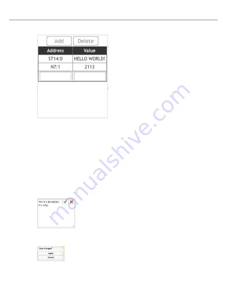
Add Initialization Files button will insert predefined strings and integers that are initialized when the PLC starts.
Integers are stored in N7:X files and must be a Decimal number in the range from 32767 to -32768. Strings are
stored in ST14:X files and their values must be ASCII characters. Maximum string length is 80 characters plus a
carriage return and line feed (CRLF). When string files are written they are displayed in capital letters, but if they
were writen in lower case they will be stored in lower case.
The Add Rung button adds another rung to the bottom of the ladder.
Zoom In and Out allows the user to adjust the size of the view.
To move a rung, select the rung by clicking it with the mouse and clicking on one of the green move icons. The
rungs may be moved up or down in single steps using the single arrow icons or to the top or bottom using the
multiple arrow icons.
The red circle with the X delete icon is available for all items on the rung. Select the item to be deleted by clicking
it with the mouse and then click the delete icon.
The Add Description icon is available for all items on the ladder. Select the item by clicking it with the mouse and
then click the Add Description icon. Type in a description and click the green check icon to save it or the red X
icon to discard it.
While editing the ladder the Save or Cancel dialog box appears. Press the Apply button to save the changes.
Press the Cancel button to discard the changes. When adding Initialization Files the window must first be saved
by clicking Apply and then the ladder logic must be saved by clicking Apply again.
7.3.2 Instruction Box
Each instruction has a box to contain its parameters and their values. Each box contains a Name field and a
Summary of Contents for QB Expert
Page 8: ......
Page 23: ...Introduction Instruction Manual 15 ...
Page 24: ......
Page 36: ......
Page 37: ...3 QB Expert Alpha Controller Programming SETUP Area SERVICE Area ANALYZE Area ...
Page 94: ......
Page 109: ...Instruction Manual 101 ...
Page 110: ......
Page 123: ...Instruction Manual 115 Tool Operation ...
Page 124: ......
Page 132: ...Input and Output Connector QB Expert Alpha Controller 124 Inputs example ...
Page 133: ...Controller Connections Instruction Manual 125 Outputs Sourcing example ...
Page 157: ...Controller Connections Instruction Manual 149 ...
Page 158: ...MODBUS TCP QB Expert Alpha Controller 150 ...
Page 175: ...Embedded PLC Instruction Manual 167 ...
Page 176: ......
Page 183: ...Multiple Spindle Instruction Manual 175 ...
Page 184: ... QB Expert Alpha Controller 176 ...
Page 201: ...Instruction Manual 193 Maintenance ...
Page 202: ...QB Expert Alpha Controller 194 ...
Page 203: ...10 QB Expert Alpha Controller Appendix A Torsion Compensation Angle Validation ...
Page 206: ......
Page 207: ...11 QB Expert Alpha Controller Glossary ...
Page 210: ......


