


99
B
A
ii
C
D
A.0500.251 – IM-TL/13.00 EN (08/2009)
12.2.4 Setting and operating – Spring loaded and spring loaded - air lifted
Since the opening pressure of the relief valve is depending on the viscosity of the
pumped medium, the setting of the relief valve should be done while the pump is fitted
in the installation. To be able to do so there must be a pressure gauge installed as close as
possible to the pump discharge port and a valve must be foreseen in the discharge line to
adjust the discharge pressure.
To adjust the set-pressure of valve do as follows:
• Remove the plastic plug at the front of the valve
• Use the retainer tool to turn the adjusting screw counter-clockwise until the spring is
completely relieved
• Connect the pressure gauge to the discharge line and open the discharge valve
completely
• Start the pump
• Use the retainer tool to turn the adjusting screw clockwise until the maximum spring
setting is reached (the valve is blocked). While doing this, check on the pressure
gauge that the pressure does not rise above the maximum allowable pressure of the
pump.
Plastic plug
Retainer tool
Valve
adjusting
Pressure gauge
Valve
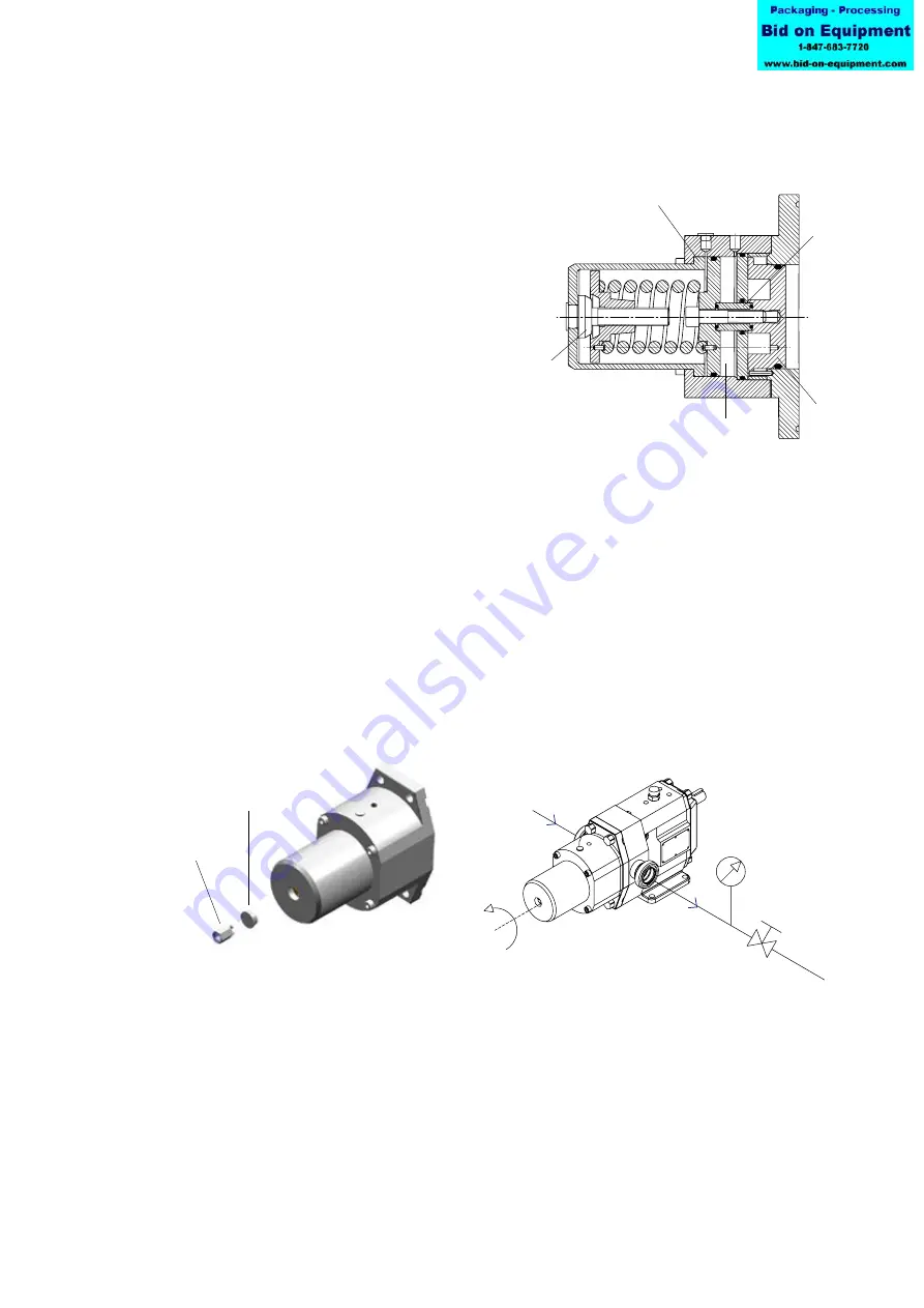
12.2.3.2 Spring loaded - air lifted with CIP/SIP valve function
Fig 6:
Safety relief valve –
Spring loaded - air lifted with CIP/SIP valve function
Fig. 6 shows the valve completely
opened. The pressure inside chamber
(ii) has forced the piston (C) and the
valve head (A) which is connected to
it to the left against the force of the
spring.
To operate the CIP/SIP valve function
chamber (ii) must be pressurized with
6 bar, which is the normal pressure
of air supply systems. This way it is
ensured that the valve is opening far
enough for CIP/SIP cleaning
purposes.
The pressure is acting on the CIP/
SIP valve piston (C). By doing that
the CIP/SIP valve piston (C) and the
valve head (A) which is connected to
it via the spacer sleeve (D) will move
against the force of the spring.
To resume the safety relief valve
function, cylinder (ii) must be
completely relieved.