


98
B
A
C
D
C
D
B
A
A.0500.251 – IM-TL/13.00 EN (08/2009)
12.2.3 Safety relief valve - Spring loaded - air lifted
12.2.3.1 Spring loaded - air lifted
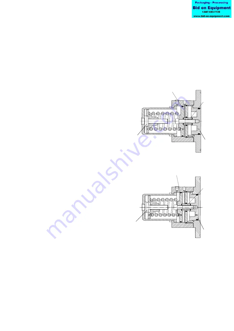
Fig. 4 and 5 are showing the design of the spring loaded - air lifted safety relief valve.
The valve head (A) is subjected to the fluid pressure in the rotor case on one side and by
spring force on the other side. The spring is not acting directly on the valve head (A) but
via piston (C) and spacer sleeve (D).
By turning the spring adjusting screw (B) the compression of the spring is modified and
the opening pressure of the safety relief valve can be adjusted. To turn the spring
adjusting screw (B), the retainer tool delivered with the pump must be used.
Fig. 4 shows the safety relief valve completely clo
-
sed. The valve head (A) is in line with the front
face of the pump cover and the CIP/SIP valve
cylinder is completely relieved.
The setting pressure of the valve has been
adjusted by compressing the spring via the
spring adjusting screw (B).
Fig 4:
Safety relief valve –
Spring loaded - air lifted completely closed
Fig. 5 shows the valve partly opened. The
medium pressure inside the rotor case
has forced the valve head (A) to the left
against the force of the spring via the
distance sleeve and the CIP/SIP piston
valve.
Fig 5:
Safety relief valve –
Spring loaded - air lifted partly opened