


45
0701
0660
0520
0172
0651
0190
4
2
7
5
3
1
8
6
4
2
5
3
1
6
11
13
3
5
12
14
7
2
9
4
15
1
6
8
10
TL1
TL2
0701
0660
0190
0652
A.0500.251 – IM-TL/13.00 EN (08/2009)
Common for TL1, TL2, TL3 and TL4
7. Place bearing covers (0121) and secure them with the screws (0510).
8. Secure the screws with Loctite 243.
TL1 and TL2
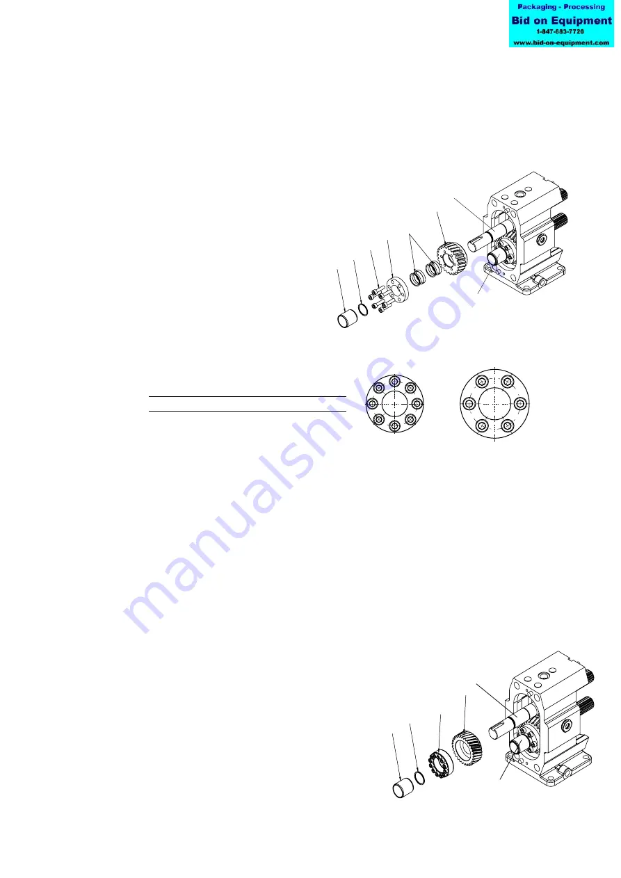
9. Place the gear (0190), with locking elements (0651) and
pressure flange (0172) on the lay shaft.
10. Check that the locking elements are clean,
lubricate them with oil and fit them in place.
Use a torque wrench to tighten the screws
(0520) with the specified torque
following the tightening sequence
shown below.
11. Now tighten the screws (0520) of the locking element in the same way as described
for the lay shaft.
12. Place the gear (0190), with locking elements (0651) and pressure flange (0172) on
the drive shaft.
13. Position the shafts by turning the drive shaft manually as shown in fig
"Shaft posittion". Put the shaft sleeves and rotors on the shaft.
14. Check the clearances between the rotors after tightening the locking elements. See
section 3.1 Rotor clearances.
15. Put the circlips (0660) on the shaft
16. Heat inner ring of the bearing up to 100°C and push them on both shafts against the
circlips.
Continue with point 18.
TL3 and TL4
10. Place the gear (0190) with locking assembly (0652) on the
lay shaft.
11. Use a torque wrench to tighten the screws of
the locking assembly with the specified torque
following the tightening sequence shown below.
12. Place the gear (0190) with locking assembly
(0652) on the drive shaft.
Drive shaft
Lay shaft
Pump
Description
M [Nm]
TL1
Hexagon screw DIN 912 M5x20 (12.9)
8.5
TL2
Hexagon screw DIN 912 M6x25 (12.9)
14
Drive shaft
Lay shaft