


48
0010
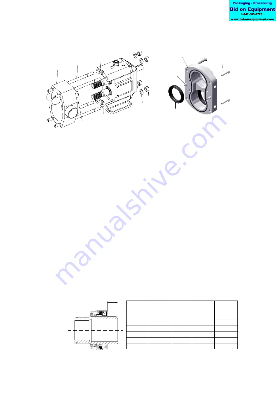
0552
0565
0455
0456
0101
0565
0890
0561
0180
0512
X
A.0500.251 – IM-TL/13.00 EN (08/2009)
Extra for TL4 with flushing cover
Fit the V-seals (0925) on the shaft ensuring they are pushed properly against the back of
flushing cover.
4.7.4 Rotor case assembly
1. Screw the stud bolts (0552) in the rotor case in case they have been removed.
2. Put the rotor case in position by smoothly tapping with a plastic hammer on it. Be
sure that the pins (0565) are in correct position.
3. Place the washers (0456) and tighten the cap nuts (0455) on the stud bolts (0552).
Note
! Be sure to tighten the cap nuts (0455) with the correct torque (See section 4.5
Tightening torques for nuts and screws).
Extra for TL4 with flushing cover
Ensure that the V-seals are pushed properly against the back of flushing cover.
4.7.5 Seal assembly
4.7.5.1 Single mechanical seal - general
1. Put O-ring (0083) in the rotating part (0081) of the seal. Position the rotating part on
the shaft sleeve to the correct setting distance (see table).
TL4
When assembling the rotating part of the seal on the shaft sleeve, position the set screws
of the seal over the radial holes on the shaft sleeve.
When replacing the shaft sleeve drill radial holes 1 mm deep, Ø 5 mm through threaded
holes in rotating part of the seal, finally locking with the set screw, using Loctite 648.
Burgmann *) Roplan **)
Burgmann *)
x
x
x
Pump type
[mm]
[mm]
Pump type
[mm]
TL1/0039
15.9
–
TL3/0234
32
TL1/0100
9.9
–
TL3/0677
20
TL1/0139
9.9
–
TL3/0953
20
TL2/0074
25
29.4
TL4/0535
63.9
TL2/0234
13
17.4
TL4/2316
14.9
TL2/0301
13
17.4
TL4/3497
14.9
*) Seal marking: Burgmann
**) Seal markning: SPX Process Equipment