


96
A.0500.251 – IM-TL/13.00 EN (08/2009)
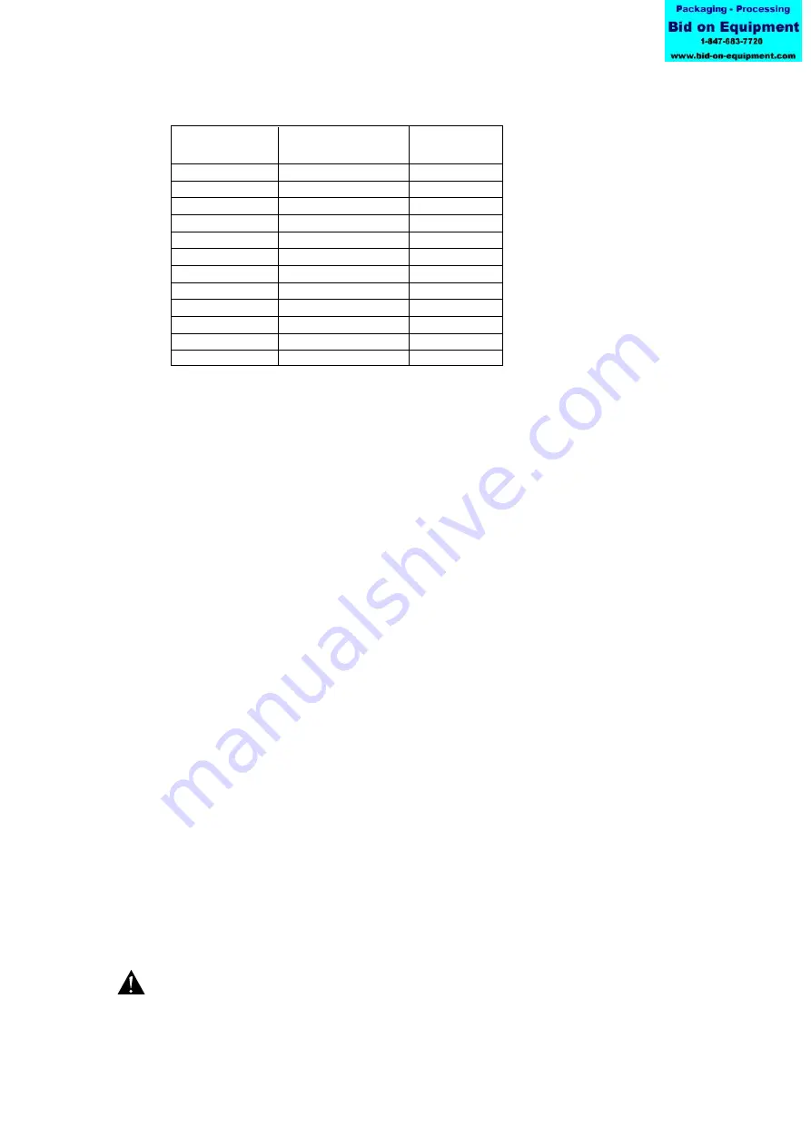
Following pressure limitations are applicable for TopLobe pumps
12.2.1 General description
Significant for all SPX Process Equipment safety relief valves is that the valve head is
built directly into the pump cover. In this way the valve is of the highest hygienic design
and easy to clean or check. The head has been designed to maximize the flow passage
section and to minimize pressure losses as well as allow particles to pass through. When
the valve head is opening, it creates a short cut between discharge and suction side of
the pump. On the valves equipped with air-lift function the valve head can be opened to
create a by-pass to reach the necessary flow-passage for CIP or SIP cleaning.
The valve head is covering part of the discharge side as well as the suction side of the
pump. It is also covering most of the front face of the rotors. The pressure distribution in
this area is depending on the properties of the pumped media. The differential pressure
on the pump is influencing the load that is acting on the valve head. The set value of the
spring or air pressure is balancing the valve head. The properties of the pumped media,
the design of the application as well as the process influences the load acting on the valve
head. These are the main reasons why the valve setting should not be done in the factory.
The setting of the valve should be carried out on site under proposed duty conditions for
which the pump and valve were selected.
When the differential pressure of the pump becomes higher than the valve settings, the
valve head will open. Due to the large size of the valve head, the full capacity of the
pump can pass through the valve from the discharge back to the suction side. With the
correct setting it is not possible to overpressure the pump under no circumstances.
If the pump is working against a closed discharge valve the medium circulates inside the
pump via the relief valve. The hydraulic power and the friction losses are transformed to
thermal energy and the temperature of this relatively small volume of circulating fluid
will rise if the pump continues to operate for an extended period of time. In severe cases
this may result in temperatures exceeding the operating limits of the pump or in
vaporization of the fluid, both of which should be avoided. For these reasons, the valve
should only be used as a safety relief valve and not as flow control valve.
When the valve is activated an unforeseen operating condition has occurred. The reason
for the system pressure increase should be investigated and corrected, as continuous
operation of the pump with the valve open is not allowable and may cause severe
damage to the pump.
Under no circumstances attempt should be made to dismantle a safety relief valve when
the spring pressure is not relieved, when it is still connected to a pressurized air supply or
is mounted on the pump while the pump is operating. Serious personal injury or pump
damage may occur.
Max differential
Max operating
pressure
pressure
Pump type
[bar]
[bar]
TL1/0039
22
25
TL1/0100
12
15
TL1/0139
7
10
TL2/0074
22
25
TL2/0234
12
15
TL2/0301
7
10
TL3/0234
22
25
TL3/0677
12
15
TL3/0953
7
10
TL4/0535
22
25
TL4/2316
12
15
TL4/3497
7
10