


49
0096 0550 0084
0182
0095
0895
0540
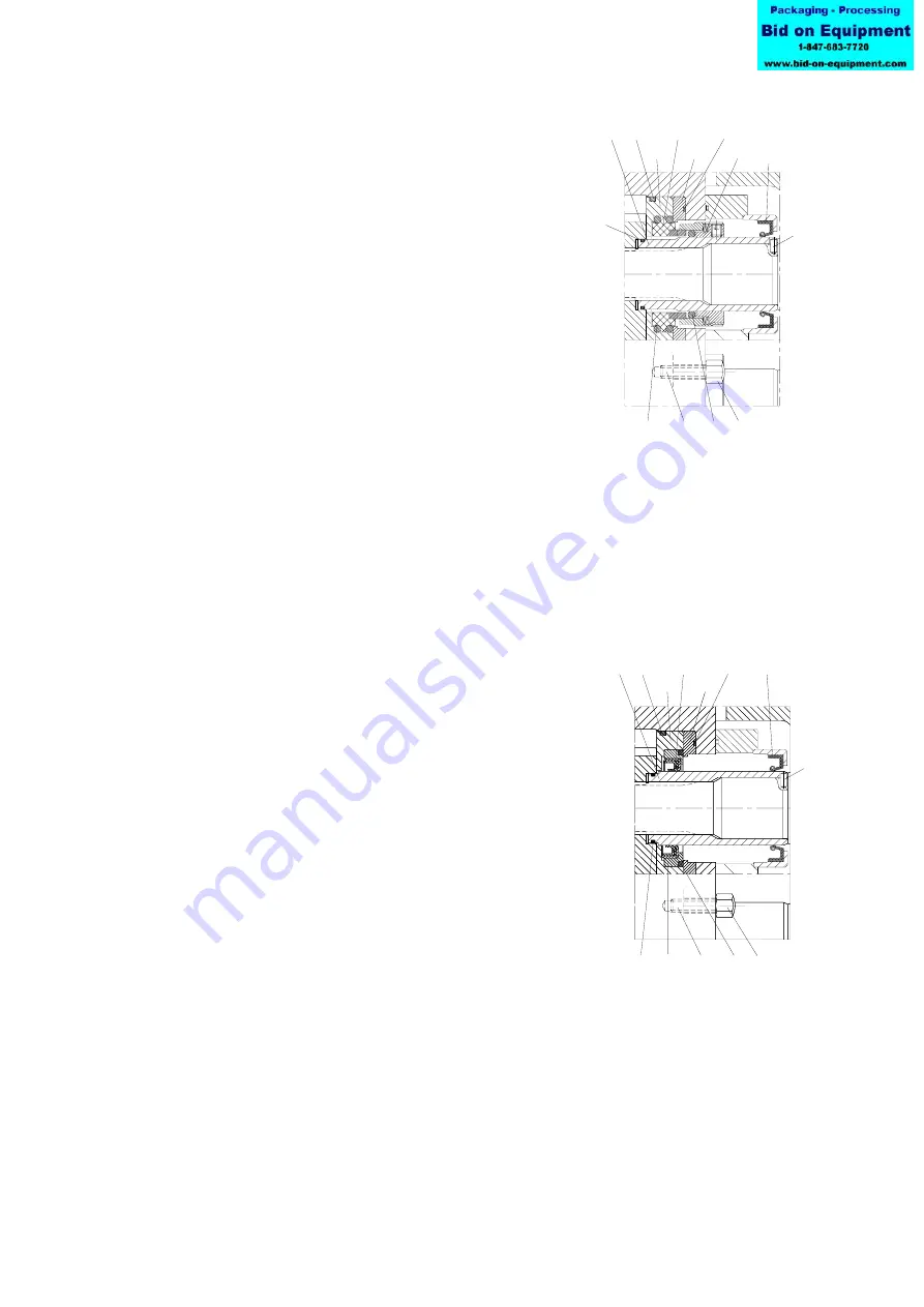
LIP SEAL
0090
0890
0804
0802
0130
0936
SINGLE MECH. SEAL
0095
0080
0090
0182
0081
0083
0082 0550
0802
0130
0540
0804
0890
0936
A.0500.251 – IM-TL/13.00 EN (08/2009)
4.7.5.2 Single mechanical seal
1. See point 1 in section 4.7.5.1
2. Put the shaft sleeve (0130) with the O-ring (0804) on
the shaft. Check the position of the lip seal (0890) in
case of a flushing cover. Do this for each shaft.
3. Check that pins (0936) fit in the groove of the shaft
sleeve.
For pumps without positioning plate (0095), go to point 5.
Pumps with positioning plate (0095)
4. Place the positioning plate (0095) with O-ring (0182) in
the rotor case.
5. Place both stationary parts (0080) with O-rings (0082)
in the seal cover (0090). Take care not to damage the
O-rings.
6. Position the seal cover with O-ring (0802) in the rotor
case and secure it with cap nuts (0540) on the stud bolts
(0550).
4.7.5.3 Lip seal
1. Place lip seals (0895) by using Loctite 648 in support
rings (0096). Next put both support rings with O-rings
(0084) into seal cover (0090).
For TL3 positions (0096) and (0084) not applicable.
For pumps without positioning plate (0095), go to point 3.
Pumps with positioning plate (0095)
2. Place the positioning plate (0095) with O-ring (0182)
in the rotor case.
3. Position the seal cover with O-ring (0802) in the rotor
case and secure it with cap nuts (0540) on the stud bolts
(0550).
4. Put the shaft sleeves (0130) with the O-ring (0804) on
the shaft. Check the position of the lip seal (0890) in
the case of a flush cover.
5. Check that the pins (0936) fit in the groove shaft sleeve.