


40
0010
0552
0565
0455
0456
0101
0565
0561
0512
Double mechanical seal
0095
0130 0090
0182
0553
0087
0540
0086
0080
0085
0083
0082
0088
0101
0890
0180
A.0500.251 – IM-TL/13.00 EN (08/2009)
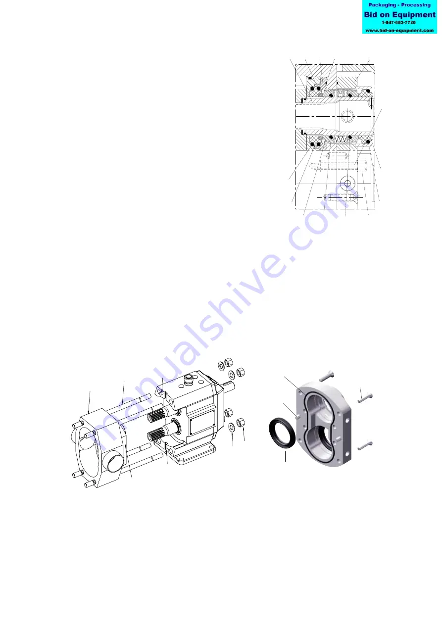
4.6.2.4 Double mechanical seal
1. Unscrew the cap nuts (0540) from the stud bolts (0553).
2. Remove the seal cover (0090) by pushing from the
rear end on the stud bolts.
3. Remove the first stationary part (0080) and O-rings
(0082) of both mechanical seals from seal cover.
Pumps without positioning plate (0095), got to point 5
Pumps with positioning plate (0095) - TL2/0074 +
TL3/0234
4. Remove positioning plate (0095) and O-ring (0182)
from the rotor case
5. Remove the shaft sleeves (0130) together with the
complete rotating part of the mechanical seal.
6. Take care not to loose the springs of the rotating part.
(TL2/0074, TL2/0234, TL2/0301, TL3/0234,
TL3/0677, TL3/0953, TL4/0535, TL4/2316, TL4/3497)
7. Remove the second stationary part (0087) of the mechanical seal with O-rings (0086)
from the flushing cover (0101).
8. Remove both seal faces of the rotating parts (0088) with O-rings (0083 and 0085)
from the shaft sleeves.
9. Remove the drivers of the rotating part from the shaft sleeves.
4.6.3 Rotor case and Flushing cover disassembly
1. Unscrew the cap nuts (0455) on the back of the pump.
Remove the washers (0456).
2. Remove rotor case (0010) by tapping with a plastic hammer on the stud bolts (0552).
Note! If a flushing cover (0101) is installed, it can be disassembled from the rotor case by
removing the screws (0512) after disassembly of the rotor case. The flushing cover is posi-
tioned with pins (0561).
For flushing cover service, remove lip seals (0890) and O-ring (0180).