


46
4
2
7
5
3
1
8
6
4
2
5
3
1
6
11
13
3
5
12
14
7
2
9
4
15
1
6
8
10
=
=
TL3, TL4
TL1, TL2, TL3
TL4
0880
0880
A.0500.251 – IM-TL/13.00 EN (08/2009)
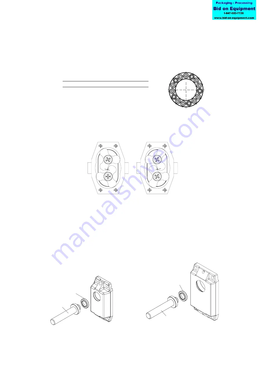
13. Position the shafts by turning the drive shaft manually as shown in fig
"Rotor position". Put the shaft sleeves and rotors on the shaft.
14. Now tighten the screws of the locking assembly in the same way as described for the
lay shaft.
15. Check the clearances between the rotors after tightening the locking elements. See
section 3.1 for Rotor clearances.
Only TL3
16. Put the circlips (0660) on the shaft.
TL3 and TL4
17. Heat inner ring of the bearing up to 100°C and push them on both shafts. (For TL3
against the circlips)
Continue with point 18.
18. Place the lip seal (0880) in the gearbox cover by using tool.
Tightening torque
Pump
Description
M [Nm]
TL3
Hexagon screw DIN 912 M6x18 (12.9)
14
TL4
Hexagon screw DIN 912 M8x22 (12.9)
21
‘‘Rotor position’’
Tool
Tool