Section 3: Operation
Page 3-8
NetClock/GTP Instruction Manual
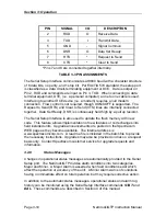
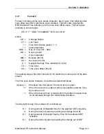
Per EIA/TIA-574 standard, the NetClock/GTP Serial Comm ports are classified a
data circuit-terminating equipment or DCE. Data is output on Pin 2, RXD and
time commands are input on Pin 3, TXD. When connecting to data terminal
equipment, DTE, (i.e. a personal computer) a one-to-one cable is used.
Interfacing to a DCE requires reversing Pins 2 and 3 or a null modem. The Serial
Comm ports require no flow control. The Request to Send and Clear to Send
signals are internally connected together, and the DSR signal is held high
through a pull-up resistor. The character structure is set for no parity, 8 data bits
and 1 stop bit.
3.2.6
RS-485 Remote Output
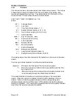
The NetClock/GTP Remote Output provides a continuous RS-485 once-per-
second time data stream in the selected data format. There are five time data
format selections and one position data stream in NMEA 0183 format available.
Refer to Section 3.3 for a complete description of the data format structures.
In addition to data formats, baud rate and UTC time difference of each output is
selectable. The command
REM1
configures the port setup. Refer to Section 4
for a complete description of this command.
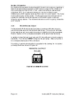
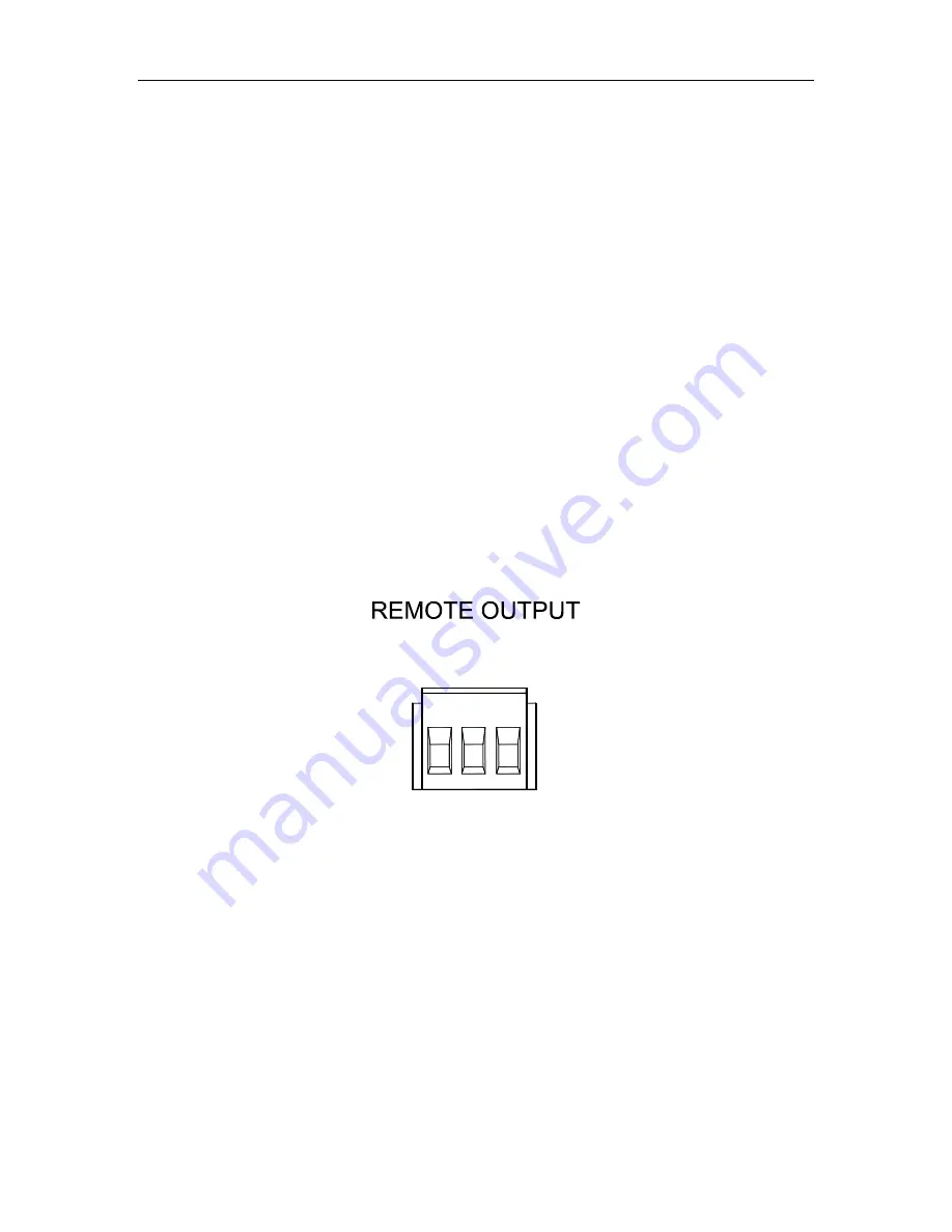
The mating 3-position terminal block is supplied in the ancillary kit. Connector
pin assignments are shown in Figure 3-5.
RS-485
+ - G
3
1 2
FIGURE 3-5 REMOTE OUTPUT

