background image


Section 3: Operation 


NetClock/GTP Instruction Manual  

Page 3-5 


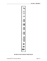
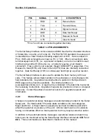
FIGURE 3-2 NETCLOCK/GTP REAR PANEL 

Summary of Contents for 8183A GTP

Page 1: ...Y 14623 PHONE 585 321 5800 FAX 585 321 5219 www spectracomcorp com Copyright 2003 Spectracom Corporation All rights reserved Contents of this publication may not be reproduced in any form without the...

Page 2: ...l make the repairs or replacement of components and charge its then current price which buyer agrees to pay Spectracom shall not have any warranty obligations if the procedure for warranty claims is n...

Page 3: ...Specifications 1 7 1 5 11 2 Mechanical Specifications 1 8 1 5 12 Model 8226 Impulse Suppressor 1 8 1 5 13 Model 8227 Inline Amplifier 1 8 1 5 14 MP10 0000 0001 Grounding Panel 1 8 1 5 15 CA07xxx GPS...

Page 4: ...3 18 3 3 6 Format 90 3 19 3 4 REMOTE OUTPUT USAGE 3 21 3 4 1 RS 485 Guidelines 3 21 3 4 2 Connection Method 3 22 3 4 3 Termination 3 30 SECTION 4 SOFTWARE COMMANDS 4 0 INTRODUCTION 4 1 4 1 ANTENNA CA...

Page 5: ...ON TROUBLESHOOTING 5 1 5 1 1 No Reception 5 1 5 1 2 Low GPS Quality 5 2 5 2 OSCILLATOR ADJUSTMENT 5 4 5 2 1 Adjustment Procedure 5 4 APPENDIX A FAA IRIG CODE DESCRIPTION A 0 INTRODUCTION A 1 A 1 MODEL...

Page 6: ...RIG CONNECTOR 3 4 FIGURE 3 4 SERIAL COMM PIN NUMBERING 3 5 FIGURE 3 5 REMOTE OUTPUTS 3 6 FIGURE 3 6 RS 485 OUTPUT 3 7 FIGURE 3 7 PIN NUMBERING 3 7 FIGURE 3 8 ONE WAY BUS INSTALLATION 3 22 FIGURE 3 9 S...

Page 7: ...BLE 3 5 CABLE SOURCES FOR RS 485 LINES OVER 1500 FEET 3 21 TABLE 3 6 CABLE SOURCES FOR RS 485 LINES UNDER 1500 FEET 3 22 TABLE 4 1 ALPHABETICAL LIST OF COMMANDS 4 2 TABLE 5 1 TYPICAL ANTENNA CABLE RES...

Page 8: ...9 ONE WAY BUS INSTALLATION 1way wmf FIGURE 3 10 SPLIT BUS CONFIGURATION Splitbus wmf FIGURE 3 11 TIMEVIEW RS 485 INTERFACE 81838177 pcx FIGURE 3 12 MODULAR JACK INTERFACE Gpsmodjk pcx FIGURE 3 13 MOD...

Page 9: ...SECTION 1 GENERAL INFORMATION 1 0 INTRODUCTION 1 1 FEATURES 1 2 WARRANTY INFORMATION AND PRODUCT SUPPORT 1 3 MANUAL ERRATA AND SPECIAL DOCUMENTATION 1 4 UNPACKING 1 5 SPECIFICATIONS...

Page 10: ...s a redundant system of highly accurate and stable atomic clock sources The satellite s timing orbital position and other system parameters are monitored and controlled by ground stations maintained b...

Page 11: ...g pages of this manual Should it become necessary to exercise the warranty contact Spectracom Corporation to obtain a replacement or service Spectracom continuously strives to improve its products and...

Page 12: ...ts If there is damage to the carton that results in damage to the unit contact the carrier immediately Retain the carton and packing materials in the event the carrier wishes to witness the shipping d...

Page 13: ...ve Availability SA on Antenna Connector BNC female 1 5 2 Display Display Type Red LED Digit Height 0 8 inches for day of the year hours and minutes 0 56 inches for seconds Display Options 12 or 24 hou...

Page 14: ...once per second output Connector DB9 female pin assignments conform to EIA TIA 574 standard data communication equipment DCE Flow control is not supported Character structure ASCII 1 start 8 data 1 s...

Page 15: ...ock indicator and error flags between Position Identifiers P5 and P6 and removal of the straight binary seconds data Accuracy 2 microseconds of UTC when locked to GPS Connector DB25 Male Connector pin...

Page 16: ...itive V Black is negative V 1 5 10 Mechanical and Environmental Dimensions 1 75 H x 19 0 W x 10 0 D inches 44 H x 483 W x 254 D mm Rack mount EIA 19 front panel mounting holes for one standard rack un...

Page 17: ...5 13 Model 8227 Inline Amplifier Connectors Type N Female Gain 20 3 dB VSWR 1 5 1 Power 3 9 VDC 7 5 1 milliamps 1 5 14 MP10 0000 0001 Grounding Panel Overall Size 12 0 L x 18 0 W x 0 75 D inches 305 H...

Page 18: ...MODEL 8225 GPS ANTENNA 2 2 ANTENNA CABLE 2 3 MODEL 8226 IMPULSE SUPPRESSOR 2 4 MP10 0000 0001 COPPER GRONDING PANEL 2 5 MODEL 8227 GPS INLINE AMPLIFIER 2 6 NETCLOCK GPS PREPARATION FOR USE 2 7 INITIA...

Page 19: ...tallation The GPS antenna must be installed outdoors in a location where an unobstructed view of the sky exists Rooftops generally make good locations due to clear overhead sky with views to the horiz...

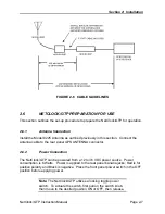
Page 20: ...ect coax suitable for outdoor use Consider the cable s weather resistance temperature range UV resistance and attenuation characteristics Do not allow the antenna cable to be placed in standing water...

Page 21: ...n 20 dB requires the use of a Model 8227 Inline Amplifier 2 3 MODEL 8226 IMPULSE SUPPRESSOR Spectracom recommends the use of an inline coaxial protector for all products with an outside antenna Spectr...

Page 22: ...amp type male N connectors These connectors can be used to splice the Model 8226 into the antenna coax The connectors are compatible with RG 213 type coax such as Spectracom CA07xxx or Belden 8267 Con...

Page 23: ...r paste Mount the grounding panel indoors preferably close to where the antenna coax enters the building and direct access to the system ground is available Refer to Figure 2 4 for installation guidel...

Page 24: ...xx or Belden 8267 Refer to Figure 2 3 for connector assembly instructions A five foot long coaxial cable is also provided with each Model 8227 This cable connects the amplifier to the surge suppressor...

Page 25: ...e antenna cable to the rear panel GPS ANTENNA connector 2 6 2 Power Connection The NetClock GTP can be powered from a 12 to 36 VDC power source Power consumption is 6 Watts Power is applied to the rea...

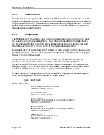
Page 26: ...ock GTP will set the clock display and time data outputs to reflect local time The default settings for all outputs are UTC time with no Daylight Saving Time rule implemented Commands to configure the...

Page 27: ...e 12 or 24 hour display format UTC or local time with or without DST corrections To allow configuration changes place the clock in Set Mode as shown below Type SM ON ent Response SET MODE ON The front...

Page 28: ...outputs to the same configuration The IRIG command structure is shown below Type IRIG TD DST ent Where TD Time Difference from UTC 00 00 12 00 Where 00 00 UTC 04 00 Atlantic 05 00 Eastern 06 00 Centra...

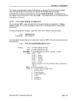
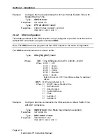
Page 29: ...or sets the Serial Comm 1 configuration and SER2 configures Serial Comm 2 The command REM1 configures the RS 485 Remote Output port The SER and REM1 command structures are shown below SER X BAUD FMT R...

Page 30: ...00 00 06 00 1 ent Response REMOTE PORT 1 BAUD RATE 9600 FORMAT 00 TIME DIFF 06 00 DST 1 2 7 INITIAL OPERATION During initial operation the GPS LOCK and TIME SYNC lamps are red The initial clock time i...

Page 31: ...I emulation 9600 baud and a character structure of 1 start 8 data 1 stop and no parity XON XOFF flow control is supported 2 8 1 GPS Signal Status The GPS Signal Status command GSS provides an instanta...

Page 32: ...ugh 8 VID is the Vehicle satellite Identification Number 1 through 37 The MODE column provides the Channel Tracking Mode for each satellite The GPS qualifying algorithm accepts only satellites having...

Page 33: ...FIED HISTOGRAM 0 00000 1 00267 2 01374 3 01344 4 00000 5 00000 6 00000 7 00000 8 00000 Q 02985 In this example the receiver tracked one satellite for 26 seconds two satellites for 287 seconds and thre...

Page 34: ...SECTION 3 OPERATION 3 0 INTRODUCTION 3 1 FRONT PANEL FUNCTIONS 3 2 REAR PANEL FUNCTIONS 3 3 DATA FORMAT DESCRIPTION 3 4 REMOTE OUTPUT USAGE...

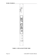
Page 35: ...ured for 12 or 24 hour format Coordinated Universal Time UTC or local time with or without Daylight Saving Time corrections The command FPF configures the front panel display format options Refer to S...

Page 36: ...Section 3 Operation Page 3 2 NetClock GTP Instruction Manual FIGURE 3 1 NETCLOCK GTP FRONT PANEL...

Page 37: ...and has recovered the GPS system almanac The entire GPS system almanac takes 12 5 minutes to transmit The time data accuracy shall now conform to specifications The lamp remains green if the receiver...

Page 38: ...ewave derived from the GPS disciplined TCXO time base Frequency accuracy is better than 1 x 10 8 0 1 Hz Signal level is 350 mVrms into 50 ohms The 10 MHz output may be used as a time base for signal g...

Page 39: ...Section 3 Operation NetClock GTP Instruction Manual Page 3 5 FIGURE 3 2 NETCLOCK GTP REAR PANEL...

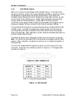
Page 40: ...four pulse width coded FAA modified IRIG B in RS 422 485 levels FAA IRIG B modifications include satellite lock indicator and error flags between Position Identifiers P5 and P6 and removal of the str...

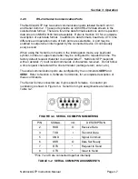
Page 41: ...any keyboard symbol number or upper case letter may be configured to request the time The factory default request character is a capital letter T NetClock GTP responds with an asterisk to all invalid...

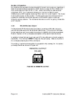
Page 42: ...ugh a pull up resistor The character structure is set for no parity 8 data bits and 1 stop bit 3 2 6 RS 485 Remote Output The NetClock GTP Remote Output provides a continuous RS 485 once per second ti...

Page 43: ...om offers many devices that accept the RS 485 data stream as an input reference These products include display clocks RS 485 to RS 232 converters NTP time provider talking clocks and radio link produc...

Page 44: ...sistor The Serial Setup Interface is also used to update the flash memory with new code This feature allows implementation of new features or code changes into field installed units Upgrade announceme...

Page 45: ...ed as a Minor Alarm is output when the following alarms and conditions exist Oscillator Adjust Warns that oscillator is operating within 10 of the minimum or maximum control setting The oscillator req...

Page 46: ...hassis to be connected to a single point grounding system Connecting the chassis to a single point ground system may be required in some installations to ensure optimum lightning protection A separate...

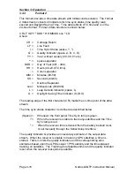
Page 47: ...cator S I D O TZ Time Zone XX Time Zone offset 00 23 The leading edge of the first character CR marks the on time point of the data stream The time sync status character I is defined as described belo...

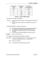
Page 48: ...Clock GTP Instruction Manual Example 271 12 45 36 DTZ 08 The example data stream provides the following information Sync Status Time synchronized to GPS Date Day 271 Time 12 45 36 Pacific Daylight Tim...

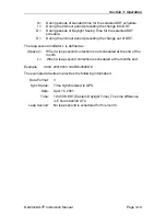
Page 49: ...MMM Month JAN FEB MAR APR MAY JUN JUL AUG SEP OCT NOV DEC YY Year without century 99 00 01 etc HH Hours 00 23 Colon separator MM Minutes 00 59 SS Seconds 00 60 The leading edge of the first character...

Page 50: ...nd Indicator space L D Daylight Saving Time Indicator S I D O The leading edge of the first character CR marks the on time point of the data stream The time sync status character I is defined as descr...

Page 51: ...he Daylight Saving Time indicator D is defined as S During periods of Standard time for the selected DST schedule I During the 24 hour period preceding the change into DST D During periods of Daylight...

Page 52: ...ds 00 60 Positive or Negative UTC offset Time Difference from UTC HHMM UTC Time Difference Hours Minutes 00 00 23 00 D Daylight Saving Time Indicator S I D O L Leap Second Indicator space L On time po...

Page 53: ...ange out of DST The leap second indicator L is defined as Space When a leap second correction is not scheduled at the end of the month L When a leap second correction is scheduled at the months end Ex...

Page 54: ...he on time point of the data stream The time sync status character I is defined as Space Whenever the front panel Time Sync lamp is green When the receiver is unable to track any satellites and the Ti...

Page 55: ...until a 3D fix is acquired ddmm mmmm n Latitude dd degress 00 90 mm mmmm minutes 00 0000 59 9999 n direction N North S South dddmm mmmm e Longitude ddd degress 000 180 mm mmmm minutes 00 0000 59 9999...

Page 56: ...7729 2249 W 1 06 03 2 00125 5 M 3F The example data stream provides the following information Time of Position Fix 15 11 19 00 UTC Latitude 43 07 0241 North Longitude 77 29 2249 West Quality 3D fix Sa...

Page 57: ...e data bus interconnections Follow the guidelines listed below when constructing the RS 485 data bus 3 4 1 RS 485 Guidelines Cable selection Low capacitance shielded twisted pair cable is recommended...

Page 58: ...00 FEET 3 4 2 Connection Method The RS 485 transmission line must be connected in a daisy chain configuration as shown in Figure 3 8 In a daisy chain configuration the transmission line connects from...

Page 59: ...quired FIGURE 3 9 SPLIT BUS CONFIGURATION Most RS 485 connections found on Spectracom equipment are made using a removable terminal strip Wires are secured by a jaw that compresses the wires when tigh...

Page 60: ...Section 3 Operation Page 3 26 NetClock GTP Instruction Manual INSERT AND TIGHTEN STRIP WIRE WRAP WIRE OVER INSULATING JACKET FIGURE 3 10 WIRE STRAIN RELIEF...

Page 61: ...485 data bus Connect the TimeView to the NetClock GTP RS 485 Output as shown in Figure 3 11 The TimeView display clocks accept only Data Formats 0 or 1 FIGURE 3 11 TIMEVIEW RS 485 INTERFACE The Model...

Page 62: ...3 MODEL 8188 RS 485 INTERFACE The Model 8180 TimeTalk provides an audio time of day announcement to time stamp voice recorders or for broadcast over radio transmitters The TimeTalk accepts only Data F...

Page 63: ...hown in Figure 3 15 FIGURE 3 15 TIMEBURST RS 485 INTERFACE 3 4 3 Termination A termination resistor is required on devices located at the ends of the RS 485 transmission line Terminating the cable end...

Page 64: ...SECTION 4 SOFTWARE COMMANDS 4 0 INTRODUCTION 4 1 4 22 RS 232 COMMAND SET...

Page 65: ...ands From Read Mode the user may select to enter Test or Set Mode Set Mode allows the user to not only view command responses but configure changes to certain NetClock GTP functions Test Mode allows t...

Page 66: ...DST Display DST rules Read 4 7 FPF Front Panel Display format Set 4 8 GSS GPS Signal Strength Read 4 9 HELP Help Display Read 4 10 IRIG IRIG Output Setup Set 4 11 LOC Location Set 4 12 LOCK GPS Lock t...

Page 67: ...000000 000 to 000999 999 microseconds To enter a cable delay place the clock in Set Mode operation issue the ACD command as follows Type ACD XXXXXX XXX ent Where XXXXXX XXX 000000 000 to 000999 999 mi...

Page 68: ...put configurations issue the CONF command as shown below Type CONF ent Default response FRONT PANEL FORMAT 24 HOUR TIME DIFF 00 00 DST 0 IRIG FORMAT FAA TIME DIFF 00 00 DST 0 SERIAL PORT 1 BAUD RATE 9...

Page 69: ...the command At the end of each page the option to display more or quit will be given Type DAL ent OR DAL P ent paged output An example of a paged alarm log is shown below TIME 14 01 03 DATE 2001 04 12...

Page 70: ...1 January 04 April DD Day of the month 01 to 31 Hyphen To set the date place the clock in Set Mode then issue the DATE command as follows Type DATE YYYY MM DD ent Where YYYY MM DD As defined above The...

Page 71: ...IG FORMAT FAA TIME DIFF 00 00 DST 0 SERIAL PORT 1 BAUD RATE 9600 FORMAT 00 REQUEST CHAR T TIME DIFF 00 00 DST 0 SERIAL PORT 2 BAUD RATE 9600 FORMAT 00 REQUEST CHAR T TIME DIFF 00 00 DST 0 REMOTE PORT...

Page 72: ...QQQ Number of seconds since the beginning of the hour the GPS signal was qualified 0 3600 Typically the receiver tracks two to three satellites when using a Model 8228 Window Mount GPS Antenna When us...

Page 73: ...E 2001 04 08 QUALIFIED HISTOGRAM 0 00000 1 00000 2 00000 3 00000 4 00000 5 00000 6 00414 7 03186 8 00000 Q 03600 TIME 18 00 00 DATE 2001 04 08 QUALIFIED HISTOGRAM 0 00000 1 00000 2 00000 3 00000 4 000...

Page 74: ...02 00 ADJ 01 00 OUT OF DATE LAST SUN OCT TIME 02 00 United Kingdom DST RULE 2 INTO DATE LAST SUN MAR TIME 02 00 ADJ 01 00 OUT OF DATE LAST SUN OCT TIME 02 00 Continental Europe DST RULE 3 INTO DATE LA...

Page 75: ...OCT NOV DEC HH MM Time of change hours minutes HH MM Amount of change hours minutes OR Type DSTX IN MM DD HH MM HH MM ent Where X Rule number 1 6 MM Month 01 12 DD Day of month 01 31 HH MM Time chang...

Page 76: ...hange 2 00am and the amount of the change 1 hour remains unchanged Follow the steps below to implement the new North American DST rule Type SM ON ent Response SET MODE ON Type DST1 IN LAST SUN MAR 02...

Page 77: ...e front panel display format place the clock in Set Mode and issue the FPF command as follows Type FPF 12 24 HH MM ent Where 12 12 Hour Display Format 24 24 Hour Display Format HH MM Time Difference f...

Page 78: ...Page 4 14 NetClock GTP Instruction Manual 06 00 05 00 04 00 03 00 02 00 01 00 00 00 01 00 02 00 03 00 04 00 05 00 06 00 07 00 08 00 09 00 10 00 11 00 12 00 11 00 10 00 09 00 08 00 07 00 06 00 12 00 FI...

Page 79: ...Tracking 3 Satellites GPS State 2D FIX DOP 04 3 Latitude N 43 07 01 541 Longitude W 077 29 15 136 Height 00102 85 meters Quality PASSED CHAN VID MODE STREN STAT 01 09 08 048 A2 02 00 00 000 00 03 00...

Page 80: ...to the geometry of the satellites used in the solution The lower the DOP value except 00 0 the lower the degree of uncertainty N North Latitude S South Latitude DDD MM SS SSS Latitude Degrees Minutes...

Page 81: ...cquire 03 Freq Acquire 08 Avail for Position 04 Bit Sync Detect STREN Signal strength value relative to SNR 000 55 The higher the number the greater the received signal STAT Channel status flag Conver...

Page 82: ...UP INFO FOR ALL OUTPUTS SERx BAUD FMT REQ TD DST SET UP SERIAL PORT REMx BAUD FMT TD DST SET UP REMOTE PORT IRIG TD DST SET UP IRIG FPF FMT TD DST FRONT PANEL SET UP LOCK HH MM SS GPS LOCK ALARM TIME...

Page 83: ...FF 00 00 DST 0 To change the IRIG output configuration place the clock in Set Mode and issue the appropriate IRIG command shown below Type IRIG TD DST ent Where TD Time difference from UTC 00 00 12 00...

Page 84: ...w position using this command has no effect Also after initial installation the receiver will keep its current position in Non Volatile RAM so that on subsequent power cycles the unit will reach first...

Page 85: ...and removes outputs placed under Lock Signature Control To view the current GPS lock time out period issue the LOCK command as shown below Type LOCK ent Default Response GPS LOCK TIME OUT 00 15 00 To...

Page 86: ...place the clock in Set Mode and issue the REM1 command as follows Type REM1 BAUD FMT TD DST ent Where BAUD Baud Rate 1200 2400 4800 9600 FMT Data Format 00 01 02 03 04 90 Refer to Section 3 3 for a c...

Page 87: ...age is included in the response An unsuccessful self test will provide a numeric code in the self test status message The entire process takes about 10 12 seconds At this point the receiver will perfo...

Page 88: ...and issue the SERx command as follows Type SERX BAUD FMT REQ TD DST ent Where X Serial Comm Number 1 2 BAUD Baud Rate 1200 2400 4800 9600 FMT Data Format 00 01 02 03 04 90 Refer to Section 3 3 for a...

Page 89: ...The time difference parameter in the Serial Comm configuration command has no effect on output time Example Configure Serial Comm 1 to respond with data format 03 whenever a is received Set the bit r...

Page 90: ...operational parameters are entered The unit times out of Set Mode and returns to Read Mode operations if no commands are issued for 15 minutes To read the Set Mode status ON or OFF issue the SM comman...

Page 91: ...elow is from a clock that is currently not receiving any qualified satellites Note that the GPS Lock and Time Sync Alarm count down timers have started but no alarms are yet asserted TIME 18 47 51 DAT...

Page 92: ...m and removes outputs placed under SYNC Signature Control To view the current sync time out period issue the SYNC command as shown below Type SYNC ent Default Response TIME SYNC TIME OUT 02 00 00 To c...

Page 93: ...00 23 MM Minutes 00 59 SS Seconds 00 60 To set the time place the clock in Set Mode and issue the TIME command as follows Type TIME HH MM SS ent Where HH MM SS As defined above Response Time message...

Page 94: ...ns to Read Mode if no commands are issued for 15 minutes Major and Minor alarms are asserted whenever the clock is in Test Mode To read the Test Mode status ON or OFF issue the TM command as shown bel...

Page 95: ...irst powered ON is recorded To retrieve version information issue the VER command as shown below Type VER ent Example Response Spectracom Corporation NetClock GTP Model 8183A Software Version 1 0 0 Da...

Page 96: ...SECTION 5 SERVICE INFORMATION 5 0 INTRODUCTION 5 1 RECEPTION TROUBLESHOOTING 5 2 TCXO ADJUSTMENT...

Page 97: ...lone and when combined DEVICE DESCRIPTION RESISTANCE 8225 Outdoor Antenna 180 ohms 8227 In line Amplifier 165 ohms 8225 and 8227 Antenna Amplifier 85 ohms TABLE 5 1 TYPICAL ANTENNA CABLE RESISTANCE VA...

Page 98: ...th Latitude DD MM SS SSS Latitude Degrees Minutes Seconds E East Longitude W West Longitude DDD MM SS SSS Longitude Degrees Minutes Seconds NOTE The approximate location is adequate zeros may be used...

Page 99: ...2 TELEVISION STATIONS WITH GPS JAMMING POTENTIAL FM radio stations while lower in radiated power can cause GPS jamming also Table 5 3 lists the potentially problem radio frequencies and their respect...

Page 100: ...error shall exceed 1 x 10 7 This section describes the oscillator adjustment procedure using a frequency counter and an RS 232 terminal The frequency counter must have a time base accuracy and measure...

Page 101: ...e by sending the SLO command as shown below Type SLO ent Response D A 3333 Record the lower limit oscillator frequency FLO ________________________ Hz 10 Subtract the lower limit frequency FLO from th...

Page 102: ...APPENDIX A IRIG CODE DESCRIPTION A 0 INTRODUCTION A 1 FAA IRIG B CODE...

Page 103: ...structure and is described in Section 4 Software Commands A 1 FAA IRIG B OUTPUT The FAA IRIG B code contains the Binary Coded Decimal BCD time of year and a Control Function CF field containing satell...

Page 104: ...Appendix A FAA IRIG Code Description Page A 2 NetClock GTP Instruction Manual FIGURE A 1 FAA IRIG B TIME CODE...

Page 105: ...IRIG B code uses five of the Control Function elements to encode satellite lock status and time error flags For a description of the status and error flag implementation refer to Table A 1 and the par...

Page 106: ...500 msec N A Locked Error 2us 1 0 0 0 0 00 16 40 Unlocked Error 1 ms 0 1 0 0 0 00 16 41 to 01 23 39 Unlocked Error 5 ms 0 0 1 0 0 01 23 40 to 13 53 19 Unlocked Error 50 ms 0 0 0 1 0 13 53 20 to 5 day...

Reviews: