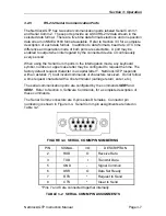
Section 3: Operation
Page 3-6
NetClock/GTP Instruction Manual
3.2.4
FAA IRIG-B Outputs
IRIG is an acronym for Inter-Range Instrumentation Group. In the late 1950’s
this group created a series of time code standards suitable for use with recording
oscillographs, magnetic tape and real time transmission. Each IRIG code
specifies a carrier frequency that is modulated to encode date and time, as well
as control bits to time stamp events. Initially, IRIG applications were primarily
military and government associated. Today, IRIG is commonly used to
synchronize voice loggers, Mode-S radar and sequential event loggers found in
emergency dispatch centers, air traffic control towers and power utilities.
The NetClock/GTP provides four pulse-width-coded FAA modified IRIG B in RS-
422/485 levels. FAA IRIG B modifications include satellite lock indicator and
error flags between Position Identifiers P5 and P6 and removal of the straight
binary seconds data. Refer Appendix A of this manual for detailed information on
the FAA modified IRIG B code.
The IRIG time data can be configured to reflect local time using the command
IRIG
. UTC time zone offset and DST rule selections are applied to all four IRIG
outputs. Refer to Section 4,
Software Commands
, for a complete description of
this command.
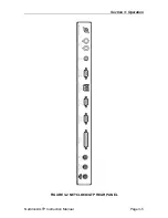
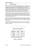
The four FAA modified IRIG B signals are output on the 25-pin series D male
connector. Connector pin numbering is shown in Figure 3-3. Pin assignments
are listed in Table 3-1.
FIGURE 3-3 IRIG CONNECTOR
OUTPUT #
IRIG +
IRIG -
Output 1
Pin 2
Pin 9
Output 2
Pin 3
Pin 10
Output 3
Pin 4
Pin 11
Output 4
Pin 5
Pin 12
Pins 1, 7, 24 and 25 are grounded.
TABLE 3-1 IRIG PIN OUT

