Section 3: Operation
Page 3-10
NetClock/GTP Instruction Manual
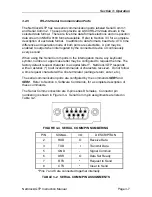
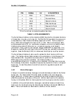
PIN SIGNAL I/O
DESCRIPTION
2 RXD O
Receive
Data
3 TXD I
Transmit
Data
5 GND -
Signal
Common
6
DSR
O
Data Set Ready
7
RTS
*
Request to Send
8
CTS
*
Clear to Send
*Pins 7 and 8 are connected together internally.
TABLE 3-3 PIN ASSIGNMENTS
The Serial Setup Interface communicates at 9600 baud with a character structure
of 8 data bits, no parity, and 1 stop bit. Per EIA/TIA 574 standard, the setup port
is classified as a data circuit-terminating equipment or DCE. Data is output on
Pin 2, RXD and commands are input on Pin 3, TXD. When connecting to data
terminal equipment, DTE, (i.e. a personal computer) a one to one cable is used.
Interfacing to another DCE device (i.e. a modem) requires a null modem
connection. Flow control is not required, though XON/XOFF is supported. The
Request to Send (RTS) and Clear to Send (CTS) lines are internally connected
together. Data Set Ready, DSR, is continuously held high by a pull up resistor.
The Serial Setup Interface is also used to update the flash memory with new
code. This feature allows implementation of new features or code changes into
field installed units. Upgrade announcements are posted on the Spectracom
WEB page as they become available. The Internet address is
www.spectracomcorp.com. A read me file is included in the batch file to provide
the necessary instructions. Upgrades may also be provided on disk on a request
basis only. Contact Spectracom customer service for upgrade requests and
information.
3.2.8 Status
Messages
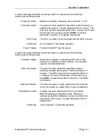
Changes in operational status messages are automatically provided to the Serial
Setup port. The NetClock/GTP divides alarm conditions into two categories,
Major and Minor. A Major Alarm is asserted when fault conditions exist which
affect the operation or accuracy of the unit. A Minor Alarm warns of conditions
having no immediate effect on total operation, but may require corrective action.
In addition to the automatic status messages, operational status and alarm log
history can be monitored using the Serial Setup Interface commands
STAT
and
DAL
. These commands are described in Section 4 of this manual.


