Section 3: Operation
NetClock/GTP Instruction Manual
Page 3-9
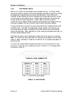
RS-485 is a balanced differential transmission requiring twisted pair cabling.
RS-485 characteristics make it ideal to distribute time data throughout a facility.
The Remote Output can provide time to 32 devices at cable lengths up to 4000
feet. Refer to Figure 3-6 for a schematic representation of the RS-485 output
driver. Relative to RS-485 specifications, the A terminal (Pin 2) is negative with
respect to the B terminal (Pin 1) for a mark or binary 1. The A terminal is positive
to the B terminal for a space or binary 0.
1
2
3
B
A
B Terminal (+)
A Terminal (-)
Shield
FIGURE 3-6 RS-485 OUTPUT
Spectracom offers many devices that accept the RS-485 data stream as an input
reference. These products include display clocks, RS-485 to RS-232 converters,
NTP time provider, talking clocks and radio link products to meet various time
applications and requirements. For information on Remote Output usage refer to
Section 3.4 of this chapter.
3.2.7
Serial Setup Interface
The Serial Setup Interface is an RS-232 communication port. Commands to
configure output signal options, set operational parameters, perform test
functions, view receiver performance and clock configuration are entered here.
Refer to Section 4,
Software Commands
, for a complete description of the
NetClock/GTP command set.
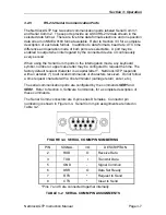
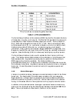
The Serial Setup Interface connector is a 9-pin series D female. Connector pin
numbering is shown in Figure 3-7. Pin assignments are listed in Table 3-3.
FIGURE 3-7 PIN NUMBERING


